My Garage
My Account
Cart
Genuine Ford Ranger Ball Joint
Control Arm Joint- Select Vehicle by Model
- Select Vehicle by VIN
Select Vehicle by Model
orMake
Model
Year
Select Vehicle by VIN
For the most accurate results, select vehicle by your VIN (Vehicle Identification Number).
10 Ball Joints found


Ford Ranger Ball Joint Assembly
Part Number: F87Z-3050-BA$50.62 MSRP: $82.00You Save: $31.38 (39%)Ships in 1-2 Business Days


Ford Ranger JOINT ASY - BALL
Part Number: KB3Z-3050-A$33.86 MSRP: $49.50You Save: $15.64 (32%)Ships in 1-2 Business Days

Ford Ranger Ball Joint Assembly
Part Number: 7L5Z-3050-A$47.14 MSRP: $76.36You Save: $29.22 (39%)Ships in 1 Business Day


Ford Ranger Ball Joint Assembly
Part Number: 6L5Z-3050-AA$47.14 MSRP: $76.36You Save: $29.22 (39%)Ships in 1 Business Day

Ford Ranger JOINT ASY - BALL
Part Number: ML3Z-3050-C$43.27 MSRP: $62.17You Save: $18.90 (31%)Ships in 1-2 Business Days


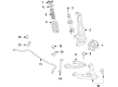
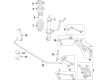
Ford Ranger Ball Joint
Ball Joint in Ford Ranger is one of the suspension and steering system that links the control arms to the steering knuckles. This design makes it possible to rotate the vehicle structure in different planes in order to respond to road challenges as well as steering instructions. Similar to other vehicles' ball joints, the Ford Ranger Ball Joint is ordinarily built of steel, with a bearing stud and socket coupled with a rubber boot to prevent contamination by dirt and to facilitate feeding of lubrication. For many years, the Ford Ranger models have traditionally adopted both loaded and unloaded ball joints whereby the loaded ball joints are able to support the weight of the vehicles while the unloaded ball joints play the role of ensuring that the vehicles are always well aligned without necessarily support the weight of the vehicles. Performance ball joints are also available that are adjustable depending on the changes in the suspension geometry especially buy modified vehicles. Some of the signs will include noise, misalignment, and abnormal tire wear, all of which will require replacement since they are critical areas that if not well maintained may compromise safety when driving.
We provide a wide range of Ford Ranger Ball Joint at the optimal prices. If you need Ford Ranger Ball Joint, you can shop with confidence on our website. All our OEM parts come with a manufacturer's warranty and are delivered to your doorstep with a fast delivery service.
Ford Ranger Ball Joint Parts Questions & Experts Answers
- Q: How to remove and install ball joints on the Ford Ranger?A:For the 2WD sub-models, the removal is done by first removing the Spindle after which unscrewing of the snap ring from the lower ball joint which practically means that the lower ball joint is removed from the spindle first. Use a special C-frame assembly tool in combination with the correct receiving cup to press the lower ball joint out of the spindle; if you do not have a suitable cup, contact a dealership or machine shop. Like the lower ball joint, the tool setup is repeated on the upper balljoint and pressed out too. When fitting the upper balljoint, use the C-frame assembly and the receiver cup to tighten the screw until fully seated, to avoid the heating of the parts. Further ontinine with the same tolls as above, press the lower balljoint into the axle until it is flush then fit the lower balljoint snap ring. For 4WD models, the tasks include the elimination of the spindle, axleshaft, and its joint, further, they need to dismantle the cotter pin and nut of the tie-rod. Shunt the snap ring from the above ball joint and the screw of pinch bolt also the cotter pin was removed and the nut was loosened of the lower ball joint. Tap on the inside of the steering knuckle close to each balljoint to release the axle arm fro mthe car and unbolt the camber adjuster sleeve, put a mark on it so that it can easily be realigned. Lose the nut on the lower ball joint and mount the steering knuckle in a vise to extract the snap ring from the lower ball joint socket. Utilize the C-frame assembly tool for pressing out the lower balljoint; do the same for the upper one. All the dust and debris around and inside the steering knuckle balljoint bores must then be removed, then the lower balljoint slot must then be aligned with the knuckle and the C-frame assembly that is to be placed in is then inserted and set in its position with a slight press. Insert lower balljoint snap ring and again perform the procedure for upper balljoint. Replace the camber adjuster on its right place so that the arrow provides correct indications for camber correction. Position the steering knuckle as the camber adjuster was set without moving it; torque the lower ball joint with a new nut; add a cotter pin. Fit the tie-rod end to the knuckle, then nut the tie-rod and put a new cotter pin to keep the nut tight. Reverse the above removal process to complete the installation and take the front end alignment.

Related Ford Ranger Parts


Browse by Year
2025 Ball Joint 2024 Ball Joint 2023 Ball Joint 2022 Ball Joint 2021 Ball Joint 2020 Ball Joint 2019 Ball Joint 2011 Ball Joint 2010 Ball Joint 2009 Ball Joint 2008 Ball Joint 2007 Ball Joint 2006 Ball Joint 2005 Ball Joint 2004 Ball Joint 2003 Ball Joint 2002 Ball Joint 2001 Ball Joint 2000 Ball Joint 1999 Ball Joint 1998 Ball Joint 1997 Ball Joint 1996 Ball Joint 1995 Ball Joint 1994 Ball Joint 1993 Ball Joint 1992 Ball Joint 1991 Ball Joint 1990 Ball Joint