Make sure this part fits

Ford F1SZ-10884-A Temperature Sender Assembly

1980-2002 Ford F1SZ10884A

Customer Questions & Expert Answers (17)
F1SZ-10884-A Ford Temperature Sender Assembly Product Photo 1 of 9
  • Part Description
    Sender Assy - Temperature
  • Base No.
    10884
  • Replaces
    DOWY-10884-A
  • Manufacturer
    Ford
Make sure this part fits
$34.68 MSRP: $56.18
You Save: $21.50 (39%)
Ships in 1-2 Business Days
1
ADD TO CART
  • Related Parts
  • Product Specifications
  • Vehicle Fitment
  • Customer Questions & Expert Answers
  • Product Specifications

    BrandGenuine Ford
    Base No.10884
    Manufacturer Part NumberF1SZ-10884-A, F1SZ10884A
    Part DescriptionSender Assy - Temperature
    Item Dimensions6.1 x 6.2 x 4.1 inches
    Item Weight0.40 Pounds
    ConditionNew
    Fitment TypeDirect Replacement
    ReplacesDOWY-10884-A
    ManufacturerFord
    SKUF1SZ-10884-A
    WarrantyThis genuine Ford part is guaranteed by Ford's factory warranty.
    Shipping & ReturnShipping Policy Return Policy
    Warning: California's Proposition 65
  • Vehicle Fitment

    Year Make Model Engine Important vehicle option details
    1986-1997 Ford Aerostar4 Cyl 2.3L, 6 Cyl 2.8L, 6 Cyl 3.0L, 6 Cyl 4.0L4AT 4R44E, 4AT 4R55E, 4AT A4LD, 5AT 5R55E, 5MT
    1980-1996 Ford Bronco6 Cyl 4.9L, 8 Cyl 5.0L, 8 Cyl 5.8L3AT C6, 4AT A4LD, 4AT AOD, 4AT E4OD, 4MT, 5MT
    1984-1990 Ford Bronco II4 Cyl 2.3L, 6 Cyl 2.8L, 6 Cyl 2.9L3AT C5, 4AT A4LD, 4AT AOD, 4MT, 5MT
    1992-1995 Ford Crown Victoria8 Cyl 4.6L4AT AOD, 4AT AOD-E
    1980-1996 Ford E-1506 Cyl 4.9L, 8 Cyl 5.0L, 8 Cyl 5.8L, 8 Cyl 6.9L Diesel, 8 Cyl 7.5L3AT C6, 3MT, 4AT 4R70W, 4AT 4R75W, 4AT AOD, 4AT E4OD, 4MT, 5MT
    1980-1996 Ford E-2506 Cyl 4.9L, 8 Cyl 5.0L, 8 Cyl 5.8L, 8 Cyl 6.6L, 8 Cyl 6.9L Diesel, 8 Cyl 7.3L Diesel, 8 Cyl 7.5L3AT C6, 3MT, 4AT AOD, 4AT E4OD
    1980-1996 Ford E-350/E-350 Super Duty6 Cyl 4.9L, 8 Cyl 5.0L, 8 Cyl 5.8L, 8 Cyl 6.6L, 8 Cyl 6.9L Diesel, 8 Cyl 7.3L Diesel, 8 Cyl 7.3L Diesel Turbocharged, 8 Cyl 7.5L3AT C6, 3MT, 4AT AOD, 4AT E4OD, 4MT, 5MT
    1996 Ford Econoline Super Duty(1996-1999)8 Cyl 5.8L, 8 Cyl 7.3L Diesel Turbocharged, 8 Cyl 7.5L3AT C6, 4AT E4OD
    1981-1994 Ford Escort4 Cyl 1.6L, 4 Cyl 1.8L, 4 Cyl 1.9L, 4 Cyl 2.0L3AT ATX, 4AT, 4MT, 5MT
    1982-1985 Ford EXP4 Cyl 1.6L3AT ATX, 4MT, 5MT
    View More
  • Customer Questions & Expert Answers

    Q:
    Is the the correct part for the attached VIN? Posted by FordPartsGiant Specialist
    A:
    You can Select Your Vehicle to check if F1SZ-10884-A fits your vehicle.
    Posted by FordPartsGiant Specialist
    Q:
    How to check Brake Light Switch,Coolant Temperature Sensor,EGR Valve Position Sensor,Intake Manifold Temperature Sensor,Knock Sensor,MAP Sensor,Mass Air Flow Sensor,Oxygen Sensors,Throttle Position Sensor on Ford Bronco? Posted by Customer
    A:
    When working with the PCM (some call it the EEC-V module) or its related harness, be careful not to touch directly any terminal on the electrical connector as static electricity could damage the PCM's delicate electronic components. It is recommended that you wear a static discharging wrist strap and do not work on electronics when relative humidity of less than 25 percent is experienced. There must be checks for general EEC-IV power relay and ground to avoid confusion or misdiagnosis. Battery powered fuel injection and electric fuel pump related components requiring 10.5 volts or above are provided by EEC relay and associated circuits. The PCM (EEC-IV) reduces input voltage to four-to-six volts for output to sensors requiring specific reference voltage (VREF). For checking fuel delivery component(s), verify proper electrical operation of the following: Dual tank models should have their fuel pumps relays, inertia switches, fuel pump(s), fuel injectors, and fuel tanks selector switch checked correctly during circuit checks for these components. Information sensors and output actuators include engine coolant temperature sensor which varies its voltage output based on temperature changes like a thermistor does. Resistances change with temperatures; coolant sensor circuit failures may set diagnostic code. For cold-started measurements of resistance values in order to establish if it is within correct ranges at operating temperature provide suitable data against which one can test the sensor's performance before confirming its current status too. Verify about 5 volts signal voltage from PCM to sensor. Always wrap new sensors' threads with Teflon sealing tape when installing them into exhaust manifolds .The Manifold Absolute Pressure (MAP) sensor senses intake manifold pressure variation then converts them into voltage output signals .Voltage varying type MAP sensors are also available as well as frequency varying types too. A failure in MAP sensor circuitry however might lead to diagnostic trouble code creation .Check reference voltage to MAP sensor after back probing wiring harness for determining type of sensor. Use a tachometer and a hand held vacuum pump to test the response of this device, verifying that it changes smoothly from one reading into another. Replace the MAP sensor if necessary results show malfunctioning. The heated oxygen sensor (HO2S) monitors the oxygen content of the exhaust gas stream, producing a voltage output that varies with air fuel ratio .Diagnostic codes indicate problems in the oxygen sensor system. Check their signal voltage stability between 0.35 and 0.55 volts at normal operating temperature. Sensor operation depends on electrical connections, outside air supply, operating temperature, and unleaded fuel use .Take special care during servicing sensors so as not to damage them. Prior replacing O2 sensors caution should be taken because they are located in exhaust manifold or pipe itself .Start and run engine briefly before removal to facilitate loosening. Make sure to disconnect battery, lift vehicle off ground , disconnect electrical connector, unscrew sensor from its position , apply anti-seize compound on threads of new sensor then install it , reconnect electrical connector.The Throttle Position Sensor (TPS) located on throttle body measures angle of throttle valve which affect how much fuel is delivered.Problems in TPS or circuitry may result in diagnostic trouble code being set To check the TPS measure signal voltage at idle and full-open throttle positions Verify reference voltage for TPS and resistance across potentiometer within it Adjust TPS when required.The Intake Manifold Temperature Sensor also known as Air Charge Temperature (ACT) sensor is a resistor changing value with air temperature placed inside intake manifold .Intake Manifold Temperature Sensor malfunction may produce diagnostic trouble code.Check reference voltage and measure resistance across terminals at different temperatures.Power steering pressure switch issues may cause timing to retard at idle or engine stalling under heavy power steering use A pressure switch that fails to open or close may impact engine performance.Verify battery voltage for power steering pressure switch along with continuity to brake light bulbs. The Brake Light Switch indicates brake application to the PCM. Issues with the Brake Light Switch or circuit may affect idle quality. Check battery voltage for Brake Light Switch and continuity to brake light bulbs.The EGR Valve Position (EVP) sensor attached to the EGR valve produces a signal indicating the EGR valve's position. Check reference voltage and resistance of EVP sensor Apply vacuum and check resistance change Replace EVP sensor if necessary .The Knock Sensor (KS) detects engine detonation, sending a voltage signal to the PCM to retard spark timing.Check reference voltage for knock sensor and simulate operating conditions for timing response Replace KS if it does not respond.Idle Air Control (IAC) or Bypass Air Idle Speed Control (BPA-ISC) solenoid controls idle speed by regulating air bypassing throttle body.Check PCM signal voltage, inspect pintle for carbon deposits, measure solenoid resistance Clean IAC valve housing during installation and install new O-ring.Mass Airflow (MAF) sensor measures air entering the engine using a hot wire sensing element .Check power supply to MAF sensor and voltage signals at idle as well as increased engine speed.Disconnect MAF sensor then test its resistance.Replace MAF sensor where necessary.The Manual Lever Position (MLP) sensor on transmission indicates gear position being sent out through PCM Let each signal wire get power before having switch adjusted Further diagnostics require specialized equipment.
    Posted by FordPartsGiant Specialist
    Q:
    How to remove and install the engine coolant temperature sensor on Ford Bronco II? Posted by Customer
    A:
    The engine coolant temperature sensor measures the temperature of the coolant and provides a signal to the PCM. When testing, disengage the wiring harness from this component and use an ohmmeter to measure its resistance. Enumerate readings obtained at both cold and hot states of the coolant on a graph. Replace it if they do not correlate with it. To remove or reinstall this part, first drain the coolant, then disconnect the battery and take off the sensor before reinstalling it again. Check for leakages after refilling it, add back water and start your car.
    Posted by FordPartsGiant Specialist
    Q:
    How to test and replace the coolant temperature sensor on the Ford Bronco II? Posted by Customer
    A:
    The coolant temperature sender is located in the left, rear side of the engine, below the cylinder head for a 2.3L engine and on the top, left front of the engine, on the intake manifold for a 2.9L and 4.0L engine. Before removing the sender from the engine block and testing it, perform the tests to ensure that it is the sender malfunctioning, and not another part of the circuit. Remove the coolant temperature sender from the engine block. Attach an ohmmeter to the sender unit by attaching one lead to the metal body of the sender unit (near the sender unit's threads) and the other lead to the sender unit's wiring harness connector terminal. With the leads still attached, place the sender unit in a pot of cold water so that neither of the leads is immersed in the water. The portion of the sender unit which normally makes contact with the engine coolant should be submerged. Measure and note the resistance. Slowly heat the pot up (on the stove) to 19D-210 degrees Fahrenheit(88-99 degrees Celsius) and observe the resistance of the sender unit. The resistance should evenly and steadily decrease as the water temperature increases. The resistance should not jump drastically or decrease erratically. If the sender unit did not function as described, replace the sender unit with a new one. Ensure that the engine is cold prior to opening the cooling system or removing the sender from the engine. The cooling system on a hot engine is under high pressure, and released hot coolant or steam can cause severe burns. Disconnect the negative battery cable. Remove the radiator cap to relieve any system pressure. Disconnect the wiring at the sender. Remove the coolant temperature sender from the engine. Coat the threads on the sender with tape or electrically conductive sealer, then install the sender. Tighten the sender to 107-143 inch lbs. (12-16 Nm). Attach the wiring to the sender and connect the negative battery cable. If necessary, add antifreeze to replace any lost coolant, then install the radiator cap.
    Posted by FordPartsGiant Specialist
    Q:
    How to remove and install the Coolant Temperature Sensor on Ford Explorer? Posted by Customer
    A:
    Allow the cooling system to completely cool down. Drain coolant from the radiator to approximately four inches below the upper radiator hose to minimize coolant loss during this procedure. Disconnect the electrical connector from the top of the sending unit. On 4.0L SOHC V6 models through 2000, the upper intake manifold must be removed to access the sending unit. It may be possible to access the sender with the thermostat housing removed. Wrap the threads of the new sending unit with Teflon tape. Remove the old sending unit from the engine. Install the new sending unit and tighten it securely. Connect the sending unit electrical connector. Refill the cooling system. Start the engine and check for leaks.
    Posted by FordPartsGiant Specialist
    Q:
    How to test and replace the coolant temperature sensor on the Ford F-250? Posted by Customer
    A:
    The coolant temperature indicator system consists of a gauge in the instrument panel and a sending unit on the engine. Check coolant level and wiring if overheating indication occurs. Gauge should start at Cold and move to Normal when engine is started. Disconnect wire from sending unit and gauge should be at Cold mark. Ground sending unit wire and gauge should move to Hot mark. If not, problem may be in gauge or wiring. If it does, sending unit is defective. Wrap new sending unit threads with Teflon tape. Remove radiator cap, replace sending unit quickly to minimize coolant loss. Tighten sending unit, attach wire, and check coolant level.
    Posted by FordPartsGiant Specialist
    Q:
    What are the instructions for replacing the engine coolant temperature sensor on the Ford Ranger? Posted by Customer
    A:
    There are two engine coolant temperature senders. One drives the temperature gauge or warning light on the instrument panel; this is generally referred to as the sending unit. The other is used by the computer to determine engine coolant temperature and adjust fuel/air mixture accordingly; this is generally referred to as a sensor. The two are easily distinguished since the sending unit for the temperature gauge has only one wire going to it, while the unit that provides information to the computer has two or three wires. On SOHC four-cylinder engines, the sending unit for the gauge or light is threaded into the driver's side of the engine block, at the rear, just below the cylinder head. On 2001 and later 2.3L engines, the sending unit is located at the rear of the engine mounted into the coolant outlet pipe. Do not mistake the temperature sending unit for the oil pressure sending unit, which is just above the coolant temperature sending unit, threaded into the cylinder head. On V6 engines, the sending unit for the gauge is located on the front lower part of the intake manifold, near the thermostat housing. Allow the cooling system to completely cool down, then open the cooling system pressure cap to relieve any pressure in the cooling system. Install the cap. This will minimize coolant loss during this procedure. Disconnect the electrical connector from the sending unit. Wrap the threads of the new sending unit with Teflon tape. Remove the old sending unit from the engine. Place your finger over the hole in the engine to minimize coolant loss. Immediately install the new sending unit and tighten it securely. Connect the sending unit electrical connector. Check coolant level and top up if necessary. Start the engine and check for leaks.
    Posted by FordPartsGiant Specialist
    Q:
    How to troubleshoot and replace a faulty coolant temperature sensor on the Mercury Capri? Posted by Customer
    A:
    Do not ground the sending unit wire directly to the engine as it may damage the gauge or instrument voltage regulator. If the coolant temperature gauge is inoperative, check the fuses first. If all gauges have similar problems such as high readings, low readings, or erratic readings, the instrument voltage regulator may be at fault and should be tested by a dealer service department or qualified electrical shop. If the temperature indicator shows excessive temperature after running a while, troubleshoot the issue. If the temperature gauge indicates "Hot" shortly after the engine is started cold or does not indicate any increase in temperature, disconnect the wire at the coolant temperature sending unit. Turn the ignition key to On, but don't start the engine. Connect a 10-ohm resistor to the disconnected wire, then ground the resistor to the engine. The temperature gauge should indicate in the Hot range. Repeat the process using a 73-ohm resistor. If the gauge indicated properly in both steps, the sending unit is bad and needs to be replaced. If the gauge did not indicate properly, the circuit may be open or the gauge may be faulty. To replace the sending unit, start by removing the cap from the radiator to release any pressure, then replace the cap. Disconnect the electrical connector from the sending unit. Apply electrically conductive sealant to the threads of the new sending unit. Unscrew the old sending unit from the engine and quickly install the new one to prevent coolant loss. Tighten the sending unit securely and reconnect the electrical connector. Refill the cooling system, run the engine, and check for leaks and proper gauge operation.
    Posted by FordPartsGiant Specialist
    Q:
    How to check and replace the Brake Light Switch,Camshaft Position Sensor,Coolant Temperature Sensor,Crankshaft Position Sensor,Intake Manifold Temperature Sensor,MAP Sensor,Mass Air Flow Sensor,Neutral Safety Switch,Oxygen Sensors,Throttle Position Sensor and Vehicle Speed Sensor on Lincoln Mark VII? Posted by Customer
    A:
    The engine coolant temperature sensor works like a thermistor that changes its power through temperature shifts, and its connection circuit can show trouble by triggering certain problems. Start by finding out how well the sensor works: take the cold and warm resistance readings, then see if warming the sensor makes the resistance go down. Check the voltage sent from the PCM to make sure the resistance values are accurate. To put in the new sensor, wait until the engine cools down fully, cover the threads with special tape, and treat the sensor gently to keep it from getting hurt. The MAP sensor takes readings from the intake manifold pressure, turns them into electrical voltage, and gives this information to the PCM to decide how much fuel to release and when to ignite the fuel. During MAP sensor electrical troubles, special fault codes show up. You can check the MAP sensor by looking at both reference voltage and signal voltage with a voltmeter, then put the system under vacuum and watch for tachometer activity. The PCM reads the oxygen content in the exhaust through the oxygen sensor. The sensor provides electrical input that tells the PCM when to add or reduce fuel in the air/fuel mixture. The MAP sensor works best when the electrical components are connected right, it gets the air it needs, runs at the right temperature, and only uses fuel without lead. Make sure the oxygen sensor gives a constant reading once it warms up, then look to see if its heating element gets power from the battery. The TPS, found on the throttle body, reads how open the throttle valve is to send correct fuel to your engine. You can examine TPS performance by measuring voltage at idle and full throttle, plus looking at PCM reference voltage. The Mass Air Flow (MAF) sensor tells the PCM how much air goes into the engine by converting it into a changing electrical voltage value. To find out if the MAF sensor is working, look for power and voltage at the signal, and check the wire for any breaks. The MLP sensor tells the PCM where the transmission is, which controls different features. Check if the MLP sensor works correctly by making sure the signal wires have the correct voltage. Combinations of problems with the Vehicle Speed Sensor lead directly to a determined fault code. To inspect the VSS, make sure the signal voltage is present at the connection. The Intake Manifold Temperature Sensor tells the PCM how warm the incoming air is, making the PCM work properly. You should measure voltage and resistance in the Intake Manifold Temperature Sensor while testing it to see how temperature affects its readings. A faulty power steering pressure switch can cause problems maintaining proper idling by monitoring fluid pressure. Your car can't tell where it's going without working crankshaft and camshaft sensor signals. Seek out a qualified mechanic to fix location problems that pop up. The brake system lets the PCM know when drivers push their brakes. When checking this part, we look for the brake light system's electricity as well as how connected points are from the brake light bulbs.
    Posted by FordPartsGiant Specialist
    Q:
    How to check and replace the Coolant Temperature Sensor on Ford Thunderbird? Posted by Customer
    A:
    This process pertains to standard analog instruments. Begin by examining the fuses if the coolant temperature gauge or light doesn't function. For an excessively high temperature indication, consider troubleshooting procedures. If the temperature gauge or light signals "Hot" soon after the engine starts, disconnect the wire at the coolant temperature sensor. Replace the sending unit if the gauge reading falls or the light turns off. High readings might indicate a shorted wire or a malfunctioning gauge. If the coolant temperature gauge doesn't register post engine warming, turn off the engine and disconnect the wire at the sending unit. Use a jumper wire to connect it to a clean engine ground. If the gauge now displays "Hot", replace the sending unit. If the gauge remains unresponsive, an open circuit or a defective gauge might be the cause. For replacement, initiate by removing the radiator cap to relieve pressure. Disconnect the electrical connector from the sending unit, and wrap Teflon tape around the threads of the new sending unit. Swiftly replace the old sending unit with the new one to avoid coolant loss. Securely tighten the sending unit and reconnect the wiring harness. Refill the cooling system and monitor for leaks and accurate gauge operation.
    Posted by FordPartsGiant Specialist
    Q:
    How to check and replace the Brake Light Switch,Camshaft Position Sensor,Coolant Temperature Sensor,Crankshaft Position Sensor,Intake Manifold Temperature Sensor,MAP Sensor,Mass Air Flow Sensor,Neutral Safety Switch,Oxygen Sensors,Throttle Position Sensor and Vehicle Speed Sensor on Lincoln Town Car? Posted by Customer
    A:
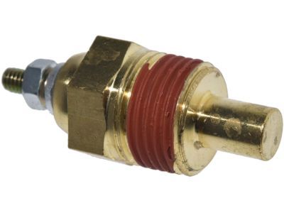
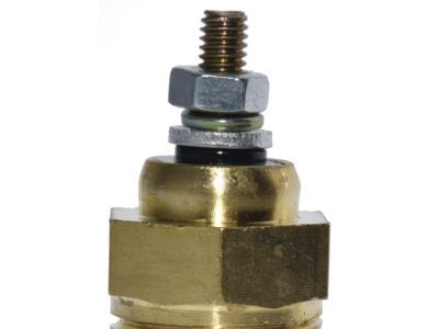
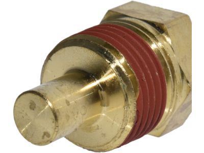
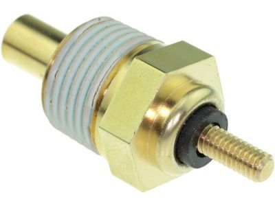
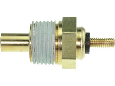
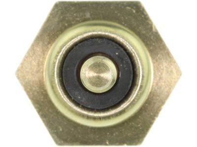
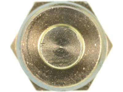
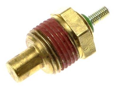
    The engine coolant temperature sensor is a thermistor that varies its voltage output based on temperature changes. Resistance values decrease as the sensor temperature increases and vice versa. Failure in the coolant sensor circuit triggers codes 21, 51, or 61 (two-digit) or 116, 117, 118 (three-digit). Resistance values should be checked while cold (58,750 to 40,500 ohms) and at operating temperature (3,600 to 1,840 ohms). Signal voltage to the sensor from the PCM should be around 5.0 volts. During replacement, wait for the engine to cool, use Teflon tape on threads, and handle the sensor with care.The Manifold Absolute Pressure (MAP) sensor monitors intake manifold pressure changes, converting them into a voltage output. A failure triggers codes 22 or 72 (two-digit) or 126, 128, 129 (three-digit). Check reference voltage (4.0 to 6.0 volts), backprobe the MAP/BP Signal wire, and apply vacuum to observe tachometer readings. Incorrect results indicate MAP sensor replacement.Oxygen sensors monitor exhaust oxygen content, adjusting air/fuel mixture. Check for a steady signal voltage between 0.35 and 0.55 volts at normal operating temperature. Codes 41, 42, 91, 92 (two-digit) or 136, 137, 139, 144, 171-178 (three-digit) indicate issues. Ensure the oxygen sensor heater receives battery voltage. Special care during service is essential.The Throttle Position Sensor (TPS) monitors throttle angle. Check for proper signal voltage (0.50 to 1.0 volts at idle, 4.0 to 5.0 volts at full throttle) and reference voltage (approximately 5.0 volts). Check potentiometer resistance (0.8 to 1.0 K ohms at closed throttle, 3.0 to 4.0 K ohms at full throttle). Replace if readings are incorrect.The Mass Air Flow (MAF) sensor, for 4.6L engines, measures air entering the engine. Check for power, signal voltage (0.2 to 1.5 volts at idle, increasing to about 2.0 volts at 60 mph), and use an ohmmeter for resistance checks. Replacement involves disconnecting the electrical connector, removing the air cleaner assembly, and uninstalling the MAF sensor.The Manual Lever Position (MLP) sensor, now Transmission Range (TR) sensor, indicates transmission gear. Check terminal connectors for attachment, verify power, and adjust if necessary. Diagnostics require special tools.The air conditioning clutch control involves PCM control of the compressor clutch. If the air conditioning does not function, check relays and switches. To test, remove the relay and bridge the battery feed and compressor clutch terminals. The Vehicle Speed Sensor (VSS) monitors speed, usually setting Code 24 if faulty. Check for signal voltage (10 volts or more). Replacement involves disconnecting the electrical connector, removing the retaining bolt, and lifting the VSS from the transmission. The Intake Manifold Temperature Sensor measures air temperature entering the engine. Check for correct reference voltage (5 volts) and resistance changes with temperature. Code 54 indicates issues.The power steering pressure switch affects idle quality. Problems may set Code 52. Check for open or closed circuits affecting engine timing.The crankshaft position sensor defines engine position for the PCM, and any issues require professional diagnosis. Replacement involves removing the electrical connector and retaining bolt.The camshaft position sensor is triggered by the camshaft sprocket's high point. Diagnostic work should be done by professionals.The Brake Light Switch informs the PCM when brakes are applied. Ensure proper voltage and continuity, and replace if needed. Brake light circuit and bulb conditions can impact idle quality.
    Posted by FordPartsGiant Specialist
    Q:
    How to check and replace the Coolant Temperature Sensor on Mercury Cougar? Posted by Customer
    A:
    This process pertains to standard analog instruments. Begin by examining the fuses if the coolant temperature gauge or light doesn't function. For an excessively high temperature indication, consider troubleshooting procedures. If the temperature gauge or light signals "Hot" soon after the engine starts, disconnect the wire at the coolant temperature sensor. Replace the sending unit if the gauge reading falls or the light turns off. High readings might indicate a shorted wire or a malfunctioning gauge. If the coolant temperature gauge doesn't register post engine warming, turn off the engine and disconnect the wire at the sending unit. Use a jumper wire to connect it to a clean engine ground. If the gauge now displays "Hot", replace the sending unit. If the gauge remains unresponsive, an open circuit or a defective gauge might be the cause. For replacement, initiate by removing the radiator cap to relieve pressure. Disconnect the electrical connector from the sending unit, and wrap Teflon tape around the threads of the new sending unit. Swiftly replace the old sending unit with the new one to avoid coolant loss. Securely tighten the sending unit and reconnect the wiring harness. Refill the cooling system and monitor for leaks and accurate gauge operation.
    Posted by FordPartsGiant Specialist
    Q:
    What are the possible reasons for the indicator light not going out after the engine starts for the 1992 Ford Crown Victoria? Posted by Customer
    A:
    The possible reasons for the indicator light not going out after the engine starts include a grounded wire between the light and the sending unit, a defective sending unit, or a faulty ignition switch.
    Posted by FordPartsGiant Specialist
    See expert answers on similar Coolant Temperature Sensor
    Q:
    Where is the sending unit for the gauge located on the 2000 Ford Ranger? Posted by Customer
    A:
    On V6 engines, the sending unit for the gauge is located on the front lower part of the intake manifold, near the thermostat housing.
    Posted by FordPartsGiant Specialist
    See expert answers on similar Coolant Temperature Sensor
    Q:
    How do you replace the Oxygen sensor, and what are the key steps for the 1999 Ford Ranger? Posted by Customer
    A:
    To replace the Oxygen sensor, disconnect the battery, raise the vehicle, remove the sensor using the appropriate tool, apply anti-seize compound to new threads, and secure the installation.
    Posted by FordPartsGiant Specialist
    See expert answers on similar Coolant Temperature Sensor
    Q:
    What are some possible reasons for the indicator light not being on when the ignition switch is turned on and the starter motor is turning for the 1989 Lincoln Mark VII? Posted by Customer
    A:
    Some possible reasons for the indicator light not being on when the ignition switch is turned on and the starter motor is turning include a burned-out bulb, faulty ignition switch, or open circuit.
    Posted by FordPartsGiant Specialist
    See expert answers on similar Coolant Temperature Sensor
    Q:
    What should happen to the indicator light as soon as the engine starts for the 1992 Mercury Grand Marquis? Posted by Customer
    A:
    As soon as the engine starts, the indicator light should go out and remain out unless the engine overheats.
    Posted by FordPartsGiant Specialist
    See expert answers on similar Coolant Temperature Sensor
    If you have any questions about this product, please don't hesitate to ask us. We will be happy to help you!

Genuine Ford Part F1SZ-10884-A, the Right Choice

To ensure reliability, purchase part # F1SZ-10884-A Temperature Sender Assembly. It is also called Coolant Temperature Sensor, Temperature Sender. OEM parts are of high quality and known for their longevity. This is because they are built to the Ford standards which are relatively high and undergo rigorous quality control testing. This part fits specific Ford Bronco, F-150, Ranger models. It fits Lincoln Mark VI, Mark VII, Mark VIII. It also fits Mercury Bobcat, Capri, Cougar.

FordPartsGiant.com is a leading supplier of genuine components and accessories such as F1SZ10884A Temperature Sender Assembly. Looking to purchase quality low-cost OEM Ford parts? You have just found the right place. For detailed Ford parts information, click here.

Why choose Ford Parts Giant

  • Dedicated Service

    Your complete satisfaction is our #1 goal

  • Lowest Prices

    Best deals on genuine OE parts from dealerships

  • Fast Delivery

    Orders are processed and delivered promptly