My Garage
My Account
Cart
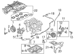
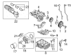
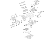
Genuine Ford Intake Manifold
Engine Intake Manifold- Select Vehicle by Model
- Select Vehicle by VIN
Select Vehicle by Model
orMake
Model
Year
Select Vehicle by VIN
For the most accurate results, select vehicle by your VIN (Vehicle Identification Number).
365 Intake Manifolds found


Ford Inlet Manifold Assembly
Part Number: CT4Z-9424-C$92.45 MSRP: $135.17You Save: $42.72 (32%)Ships in 1-3 Business DaysProduct Specifications- Other Name: Manifold Assy - Inlet; Intake Manifold
- Position: Lower
- Replaces: AT4Z-9424-F, CT4Z-9424-A


 Product Specifications
- Other Name: Intake Manifold; Manifold Assembly - Inlet
- Replaces: BC3Z-9424-BE, BC3Z-9424-B, BC3Z-9424-E, BC3Z-9424-F


Ford Inlet Manifold Assembly
Part Number: JL3Z-9424-C$362.73 MSRP: $535.00You Save: $172.27 (33%)Ships in 1-3 Business DaysProduct Specifications- Other Name: MANIFOLD ASY - INLET; Intake Manifold


 Product Specifications
- Other Name: Manifold Assembly - Inlet; Intake Manifold
- Replaces: BL3Z-9424-C, BL3Z-9424-A

 Product Specifications
- Other Name: Manifold Assy - Inlet; Intake Manifold
- Manufacturer Note: One Piece Design
- Replaced by: PU7Z-9424-A

 Product Specifications
- Other Name: Manifold Assy - Inlet; Intake Manifold
- Position: Upper
- Replaces: 4F1Z-9424-CA


Ford Inlet Manifold Assembly
Part Number: HL3Z-9424-B$89.15 MSRP: $130.33You Save: $41.18 (32%)Ships in 1-2 Business DaysProduct Specifications- Other Name: MANIFOLD ASY - INLET; Intake Manifold
- Replaces: HL3Z-9424-A


Ford Inlet Manifold Assembly
Part Number: BC3Z-9424-D$181.83 MSRP: $265.83You Save: $84.00 (32%)Ships in 1-3 Business DaysProduct Specifications- Other Name: Manifold Assembly - Inlet


 Product Specifications
- Other Name: Manifold Assy - Inlet; Intake Manifold
- Position: Upper


Ford Inlet Manifold Assembly
Part Number: BM5Z-9424-A$127.20 MSRP: $196.67You Save: $69.47 (36%)Ships in 1-3 Business DaysProduct Specifications- Other Name: Manifold Assy - Inlet; Intake Manifold


Ford Inlet Manifold Assembly
Part Number: 9C2Z-9424-A$2952.32 MSRP: $4393.33You Save: $1441.01 (33%)Product Specifications- Other Name: Manifold Assy - Inlet; Intake Manifold, Upper Manifold
- Position: Upper
- Replaces: 2C3Z-9424-AA, YC2Z-9424-BA


Ford Inlet Manifold Assembly
Part Number: FL3Z-9424-F$645.81 MSRP: $1030.00You Save: $384.19 (38%)Ships in 1-3 Business DaysProduct Specifications- Other Name: Manifold Assy - Inlet
- Replaced by: FL3Z-9424-J


Ford Inlet Manifold Assembly
Part Number: BL3Z-9424-B$111.95 MSRP: $163.67You Save: $51.72 (32%)Ships in 1-3 Business DaysProduct Specifications- Other Name: Manifold Assy - Inlet
- Replaced by: BL3Z-9424-E

Ford Inlet Manifold Assembly
Part Number: CM5Z-9424-D$43.55 MSRP: $56.67You Save: $13.12 (24%)Ships in 1-3 Business DaysProduct Specifications- Other Name: MANIFOLD ASY - INLET; Intake Manifold
- Replaces: CM5Z-9424-A

Ford Inlet Manifold Assembly
Part Number: ML3Z-9424-H$74.98 MSRP: $115.00You Save: $40.02 (35%)Ships in 1-2 Business DaysProduct Specifications- Other Name: MANIFOLD ASY - INLET; Intake Manifold
- Replaces: ML3Z-9424-D, ML3Z-9424-G, ML3Z-9424-F

Ford Inlet Manifold Assembly
Part Number: CT4Z-9424-A$92.45 MSRP: $135.17You Save: $42.72 (32%)Ships in 1-3 Business DaysProduct Specifications- Other Name: Manifold Assy - Inlet
- Position: Lower
- Replaced by: CT4Z-9424-C


 Product Specifications
- Other Name: Manifold Assy - Inlet
- Position: Upper
- Replaced by: 4L5Z-9424-A

 Product Specifications
- Other Name: Manifold Assy - Inlet; Intake Manifold
- Manufacturer Note: Upper, Lighting
- Position: Upper

 Product Specifications
- Other Name: Manifold Assy - Inlet
- Replaced by: 4L5Z-9424-A
 Product Specifications
- Other Name: Manifold Assy - Inlet; Intake Manifold
- Manufacturer Note: Upper. Plastic cover 9E434 not serviced separately., FROM 7/31/2002
- Replaces: 1F2Z-9424-AA
| Page 1 of 19 |Next >
1-20 of 365 Results
Ford Intake Manifold Parts Questions & Experts Answers
- Q: How to remove and install the intake manifold in V8 engine on Ford Bronco?A:To remove the carbureted models, begin by draining the cooling system, then remove the air cleaner and intake duct assemblies. Carefully mark and detach any emissions control connections at the air cleaner, disconnect the upper radiator hose from the thermostat housing, and disconnect the heater hose and water pump by-pass hose at the intake manifold connections. For a 7.5L engine, remove the right valve cover. Mark and disconnect the spark plug wires at the spark plugs, then remove the distributor cap along with the spark plug wires. Disconnect the primary low voltage wires from the coil, marking them for correct reinstallation, and remove the coil mounting bracket and mounting bolt. Remove the carburetor fuel inlet line from the carburetor, positioning it out of the way, and disconnect the vacuum advance hose(s) from the distributor, marking them for proper installation. Remove the distributor and any wires from sensors mounted in the intake manifold or upper thermostat housing. Remove the accelerator cable or linkage connection at the carburetor, the kickdown cable if equipped with an automatic transmission, and the pull cable and activating unit from the intake manifold if cruise control is present. Remove the vacuum hose leading to the power brake booster from the intake manifold and secure it to the firewall. If servicing the carburetor separately, remove it from the intake manifold, and disconnect the crankcase vent hose leading from the manifold to the valve cover. For fuel-injected models, remove the upper intake manifold, drain the cooling system, and remove the distributor. Label and disconnect all electrical harness connectors from lower intake manifold sensors and solenoids, as well as any vacuum hoses from the lower intake manifold. Relieve the fuel system pressure, disconnect the fuel supply and return lines from the fuel rail, and disconnect the fuel injector electrical connectors. Remove the oxygen sensor ground wire from the intake manifold stud, the upper radiator hose from the thermostat housing, and the bypass and outlet hoses from the intake manifold. Remove the coil/solenoid bracket assembly and position it out of the way. For all engines, remove the bolts retaining the intake manifold to the cylinder heads, attach lifting hooks at opposite corners, and lift the intake manifold from the engine, taking care not to damage the mating surfaces. Clean the mating surfaces of the intake manifold and cylinder heads, remove the end gaskets from the top of the engine block, and remove the oil gallery splash pan if equipped. For installation, reassemble the manifold by reversing the disassembly procedure, applying electrical conductive sealant to the temperature sending unit threads and RTV sealant to the thermostat gasket. Apply a bead of RTV sealant to the mating points at the junctions of the cylinder heads and engine block, position the new manifold end seals carefully, and ensure the intake manifold gaskets are aligned correctly with the cylinder heads. Apply a bead of RTV sealant to the interlocking corners of the intake manifold gasket and end seal, install locating pins if necessary, lower the intake manifold into position, and install the retaining bolts, tightening them in sequence to the specified torque. Reinstall the remaining components in reverse order, refill the cooling system, and start the engine, allowing it to reach operating temperature while checking for leaks and adjusting the ignition timing if necessary.
- Q: How to remove and install the intake manifold in 4.2L V6 engine on Ford F-150?A:Intake manifolds are removed by dropping the fuel pressure and also removing the air filter housing, disconnecting the cable from the negative battery terminal and drain the cooling system coalesced. Remove the heater hose clamps and set the hoses to the side, take off the EGA module vacuum hose and connector and also, remove the EGA pipe. After that, remove the MAF sensor connector, the ECT sensor harness connector, the IGN 2 heater connector, the A/C Idle command harness connector and the connector to the electronic throttle body, and the EVAP line from the upper intake manifold and the FRPT sensor harness connector and the fuel injection harness connectors. Remove the vacuum hose connector and brake booster vacuum hose from the back of the upper intake manifold, and relieve the PCV pressure by removing the PCV hoses, and the PCV valve brackets from the valve covers. Lose the upper intake manifold mounting bolts and cover the air intake ports with the shop towel. For the lower intake manifold, the IMRC connector should be disconnected, the fuel rail then the upper radiator hose, and the bypass hose then, the lower intake manifold should be unbolted by turning the bolts in a 1/4 turn until they can be unscrewed. Where there is a problem with the intake manifold, use prybar to separate the gasket, after ensuring that all bolts creating the vacuum have been unscrewed. During installation clean the mating surfaces with gasket scraper and cleaning solvents if they are required. Cleaning up through the hole of the bolt and also clearing any debris, endeavor to follow the threads and examine the gasket surfaces. While making the construction, use the RTV sealant to spread on the block surface and put the rubber seals and side gaskets in its rightful place. Place the manifold properly in its right position when the sealant is wet, so that the gaskets are not shifted off. Liberal coat the manifold bolts with oil then install them and subsequently tighten the bolts until the recommended torque is achieved in the right sequence. As for the upper intake manifold, it is necessary to replace gasket seals, put the upper intake manifold in the place of the lower intake manifold, fasten the bolts. Last but not the least, refill the cooling system and turn on the engine and look for at the intake manifold joints if there are oil and coolant leakages.
- Q: How to remove and install Intake Manifold in 3.0L V6 engine on Ford Ranger?A:To remove the intake manifold, first relieve the fuel pressure, disconnect the negative battery cable, and drain the cooling system. Next, disconnect the fuel rails and lines, capping them to prevent dirt entry. Remove the throttle body, label and disconnect all wiring, vacuum, and coolant hoses from the intake manifold, and then remove the distributor or camshaft position sensor depending on the model year. For models from 2006 and later, loosen the rocker arms to remove all pushrods, ensuring each is marked for reinstallation. Remove the manifold attaching bolts or studs using a Torx driver bit, noting their locations for reinstallation, and then take out the intake manifold, prying carefully to avoid damage. For installation, clean all old gasket material from mating surfaces, lightly oil threaded fasteners, and apply RTV sealant at the intersections of the cylinder head and block. Position the intake manifold gaskets over the tabs on the cylinder heads, install the front and rear manifold end seals, and apply RTV sealer on top of the end seals without allowing it to dry. Carefully lower the manifold into place, install the bolts and studs in the specified sequence to the correct torque, and if applicable, reinstall the thermostat housing with a new gasket. Complete the installation by reversing the removal steps, refilling the cooling system, reconnecting the battery, and running the engine to check for vacuum and fluid leaks.


Related Ford Parts

Browse by Model
Aerostar Intake Manifold Aspire Intake Manifold Bronco Intake Manifold Bronco Sport Intake Manifold C-Max Intake Manifold Contour Intake Manifold Crown Victoria Intake Manifold E-150 Intake Manifold E-250 Intake Manifold E-350/E-350 Super Duty Intake Manifold E-450 Super Duty Intake Manifold E-550 Super Duty Intake Manifold Econoline Super Duty(1996-1999) Intake Manifold EcoSport Intake Manifold Edge Intake Manifold Escape Intake Manifold Escort Intake Manifold Excursion Intake Manifold Expedition Intake Manifold Explorer Intake Manifold Explorer Sport Intake Manifold Explorer Sport Trac Intake Manifold F-150 Intake Manifold F-250 Intake Manifold F-250 Super Duty Intake Manifold F-350 Intake Manifold F-350 Super Duty Intake Manifold F-450 Super Duty Intake Manifold F-550 Super Duty Intake Manifold F53 Intake Manifold F53 Stripped Chassis Intake Manifold Fiesta Intake Manifold Five Hundred Intake Manifold Flex Intake Manifold Focus Intake Manifold Freestar Intake Manifold Freestyle Intake Manifold Fusion Intake Manifold GT Intake Manifold Maverick Intake Manifold Mustang Intake Manifold Police Interceptor Sedan Intake Manifold Police Interceptor Utility Intake Manifold Police Responder Hybrid Intake Manifold Probe Intake Manifold Ranger Intake Manifold SSV Plug-In Hybrid Intake Manifold Taurus Intake Manifold Taurus X Intake Manifold Thunderbird Intake Manifold Transit Connect Intake Manifold Transit Intake Manifold Windstar Intake Manifold