
My Garage
My Account
Cart
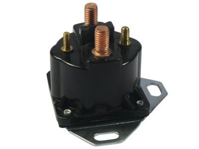
Genuine Ford F-250 Relay
Wire Relay- Select Vehicle by Model
- Select Vehicle by VIN
Select Vehicle by Model
orMake
Model
Year
Select Vehicle by VIN
For the most accurate results, select vehicle by your VIN (Vehicle Identification Number).
24 Relays found
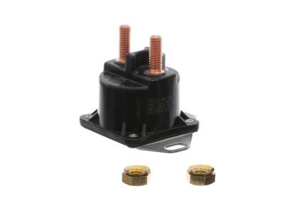
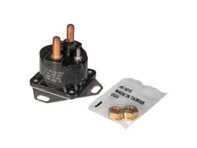
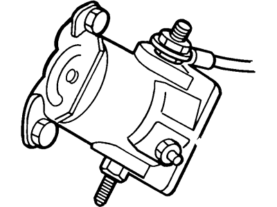
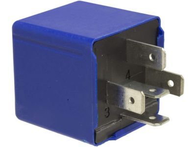
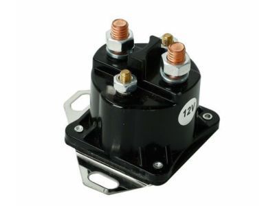
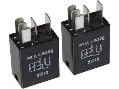
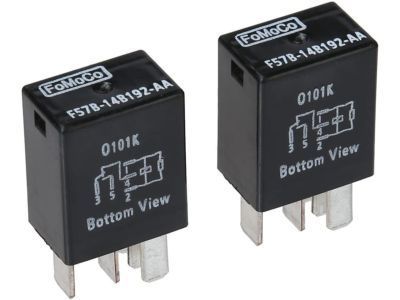
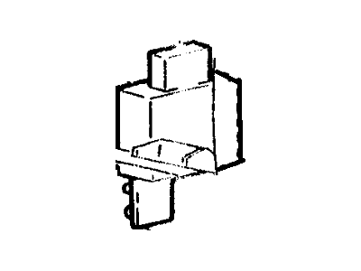
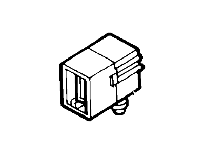
Ford F-250 Starter Motor Relay Assy
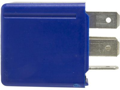
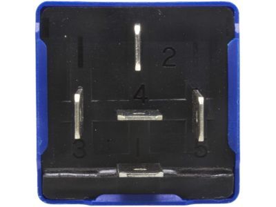
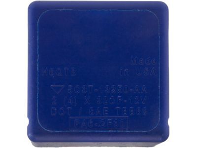
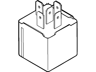
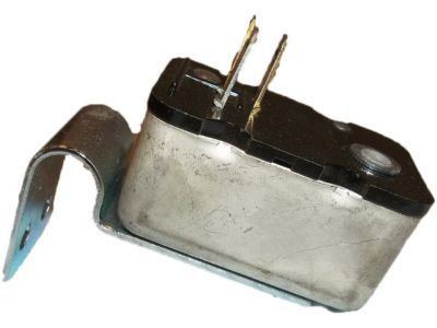
Part Number: E9TZ-11450-B$24.17 MSRP: $38.55You Save: $14.38 (38%)Ships in 1 Business DayFord F-250 Direction Indicator Relay
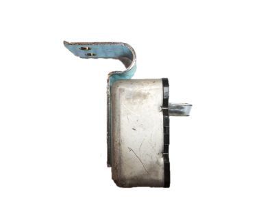
Part Number: F65Z-13350-AA$27.82 MSRP: $44.36You Save: $16.54 (38%)Ships in 1-2 Business DaysFord F-250 Glow Plug Relay Assembly
Part Number: F7TZ-12B533-CA$56.76 MSRP: $93.82You Save: $37.06 (40%)Ships in 1 Business DayFord F-250 Glow Plug Relay Assembly
Part Number: F81Z-12B533-AA$67.32 MSRP: $111.27You Save: $43.95 (40%)Ships in 1 Business DayFord F-250 Relay
Part Number: F5TZ-14N089-B$9.96 MSRP: $14.18You Save: $4.22 (30%)Ships in 1 Business Day
| Page 1 of 2 |Next >
1-20 of 24 Results
Ford F-250 Relay
We provide a wide range of Ford F-250 Relay at the best prices possible. If you need Ford F-250 Relay, you can shop with confidence on our website. All our OEM parts come with a manufacturer's warranty and are delivered to your door step with a fast delivery service.
Ford F-250 Relay Parts Questions & Experts Answers
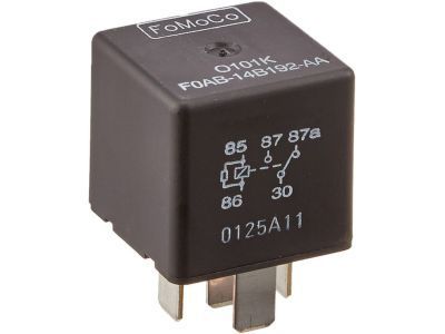
- Q: What is the general information about relays and their testing on Ford F-250?A:Some of the electrical accessories in the vehicles which employs the relay includes fuel injection system, Horns, starter, fog lamps etc by passing the signals electrically. A relay controls a high current power circuit using a low current control circuit and if the relay is faulty then the required circuit will not function as required. Some of the relays and their locations are easily identified but their functions can be found in the owner's guide. If there is a problem with the relay then the relay can be removed and tested through a relay test procedure or through a dealer service/ repair shop; bad relays are replaced as an assembly. ISO relays are most often used in these vehicles, and their terminals are numbered making the typical connections easy to identify, although there are only two basic terminal arrangements. If the circuit is to be tested, then the wiring diagram of the circuit can well be used to establish proper connections. Two pins are of relay control circuit, used for coupling the relay coil and remaining pins are of the power circuit. When it is supplied with energy the magnetic field thus closes the larger contacts of the power circuit supplying power to the loads. Control circuit is normally held by terminals 85 and 86, and certain connections may be necessary in case the element in question is a diode or resistor. Terminal 30 links to the battery voltage for circuit loads while terminal 87 links to the ground side of the circuit. To check continuity through the relay control coil an ohmmeter should be used and is recommended that testing should be done in two different polarities. Of a resistor value should be same irrespective of whether electrons are passing through it in forward or in reverse direction but in the case of a diode its impedance should be high in one direction rather than the other. Dual direction with infinite resistance calls for relay replacement. After taking out the relay, continuity should be checked at the power circuit terminals; there should be no continuity between terminal 30 and 87 when there is no power. To make the relay click, an individual should link a fused jumper wire between terminal number 86 on the coil and the positive terminal of the battery additionally, use a second jumper wire between terminal number 85 and the ground. With these connections continuity should now be present between terminals 30 and 87. If any of the above tests are not materialized by the relay, then the relay should be replaced.
