My Garage
My Account
Cart
Genuine Ford Expedition Control Arm
Suspension Arm- Select Vehicle by Model
- Select Vehicle by VIN
Select Vehicle by Model
orMake
Model
Year
Select Vehicle by VIN
For the most accurate results, select vehicle by your VIN (Vehicle Identification Number).
69 Control Arms found


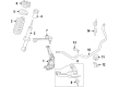
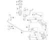
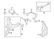
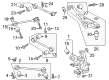
Ford Expedition Front Suspension Arm Assembly
Part Number: JL1Z-3085-C$138.38 MSRP: $223.64You Save: $85.26 (39%)Ships in 1-2 Business Days

Ford Expedition Front Suspension Arm Assembly
Part Number: 6L1Z-3084-AA$116.18 MSRP: $187.27You Save: $71.09 (38%)Ships in 1-2 Business Days

Ford Expedition Front Suspension Arm Assembly
Part Number: JL1Z-3085-A$101.82 MSRP: $223.64You Save: $121.82 (55%)
Ford Expedition Front Suspension Arm Assembly
Part Number: JL1Z-3084-A$139.08 MSRP: $207.27You Save: $68.19 (33%)

Ford Expedition Front Suspension Arm Assembly
Part Number: 9L3Z-3078-A$182.25 MSRP: $294.55You Save: $112.30 (39%)Ships in 1-2 Business Days
Ford Expedition Front Suspension Arm Assembly
Part Number: 9L3Z-3079-A$175.50 MSRP: $283.64You Save: $108.14 (39%)Ships in 1 Business Day


Ford Expedition Front Suspension Arm Assembly
Part Number: EL1Z-3078-A$209.62 MSRP: $341.82You Save: $132.20 (39%)Ships in 1-2 Business Days

Ford Expedition Front Suspension Arm Assembly
Part Number: EL1Z-3079-A$221.89 MSRP: $361.82You Save: $139.93 (39%)Ships in 1-2 Business Days

Ford Expedition Front Suspension Arm Assembly
Part Number: BL3Z-3084-A$126.00 MSRP: $203.64You Save: $77.64 (39%)Ships in 1 Business Day

Ford Expedition Front Suspension Arm Assembly
Part Number: EL3Z-3084-A$126.00 MSRP: $203.64You Save: $77.64 (39%)Ships in 1 Business Day
Ford Expedition Front Suspension Arm Assembly
Part Number: EL3Z-3085-A$126.00 MSRP: $203.64You Save: $77.64 (39%)Ships in 1 Business Day

Ford Expedition Front Suspension Arm Assembly
Part Number: 9L3Z-3085-A$126.00 MSRP: $203.64You Save: $77.64 (39%)Ships in 1 Business Day

Ford Expedition Front Suspension Arm Assembly
Part Number: 9L3Z-3084-A$126.00 MSRP: $203.64You Save: $77.64 (39%)Ships in 1 Business Day
Ford Expedition Front Suspension Arm Assembly
Part Number: NL3Z-3085-A$266.49 MSRP: $434.55You Save: $168.06 (39%)Ships in 1-2 Business Days
Ford Expedition Front Suspension Arm Assembly
Part Number: JL1Z-3084-B$128.25 MSRP: $207.27You Save: $79.02 (39%)Ships in 1-2 Business Days
Ford Expedition Front Suspension Arm Assembly
Part Number: NL1Z-3085-A$149.10 MSRP: $254.55You Save: $105.45 (42%)Ships in 1-2 Business Days
Ford Expedition Rear Suspension Arm Assembly
Part Number: JL1Z-5500-F$118.56 MSRP: $173.33You Save: $54.77 (32%)
Ford Expedition Rear Suspension Arm Assembly
Part Number: JL1Z-5500-G$103.21 MSRP: $176.18You Save: $72.97 (42%)Ships in 1-2 Business Days


| Page 1 of 4 |Next >
1-20 of 69 Results
Ford Expedition Control Arm
The Control Arm in Ford Expedition simply translates the movement of the frame to the wheels and houses other spare parts including; shocks and springs. These arms turn in relation to the road's surface and help the wheels to rotate in a vertical motion. Ford Expedition Control Arms come in different designs and forging materials; the types that are found in more advanced models are cast iron or aluminum. However, common chasis wear items such as bushings and ball joints may sometimes have to be replaced as they are relatively durable. Aluminum and high-strength steel performance control arms are also offered for the for high-speed application or for modified car models. Further, control arm bushings, and hardware are available; that can be either used to replace OE arms or adjust the mounting position for improved alignment.
We provide a wide range of Ford Expedition Control Arm at the optimal prices. If you need Ford Expedition Control Arm, you can shop with confidence on our website. All our OEM parts come with a manufacturer's warranty and are delivered to your doorstep with a fast delivery service.
Ford Expedition Control Arm Parts Questions & Experts Answers
- Q: How to remove and install the lower control arm on Ford Expedition?A:On 2WD models, when the vehicle has Air Suspension, then turn off the air suspension system by using the switch that is in the position of the right kick panel. Unscrew the lug nuts of the wheels, jack the vehicle up and hold it on jackstands and then take out the wheel. Disassemble the disc brake caliper, brake pads, caliper anchor bracket and the disc then the disc brake splash shield. Take out the shock absorber and separate the brake hose bracket with the lower control arm. Un screw the front stabilizer bar link nut. Install the compressor with the help of the appropriate coil spring compressor and compress the coil spring. Install the balljoint and screw the Steering Knuckle and ballstud nut. Install the bracket of the 4WABS front brake anti-lock sensor and screw the bolt firmly. Install the lug nuts, wheel and lug nuts, lower the vehicle and tighten the lug nuts. Install tightening of the upper arm pivot bolt nuts, front nut to be installed first, and reconnect the air suspension system where fitted. In 4WD models with air suspension system, shut it off, loosen the wheel lug nuts, lift the vehicle, put on jackstands and then undo the wheel. Removing of skid plate when fitted. When the car is equipped with a 4-wheel antilock brake system (4WABS) detach the bracket of the anti-lock sensor wire of the front brake control arm. Take off the Torsion Bar, dis-attach the shock absorber with the lower control arm and the stabilizer bar with the lower control arm. Unscrew the lower balljoint of the steering knuckle with an appropriate puller, handle the loosened ballstud nut attached to the ballstud to avoid violent separation. Take out the lower control arm pivot bolts, nuts and washers and then take out the lower control arm. Inspect the bushings in case of damage or wear. Replacement of control arm should be done when it has welded-in bushings that cannot be replaced, replaceable bushings may be used, then press with special adapters or bring control arm to a repair shop. To install, elevate the control arm into place and add the control arm pivot bolts, washers and nuts but do not tighten them fully at this stage, so that the threaded sections are facing forward. Lift the lower control arm using a floor jack until the balljoint stud is able to fit into the steering knuckle hole, add the balljoint stud nut, loosen it slightly and replace a cotter pin. Install the stabilizer bar to the lower control arm, installment to shock absorber, reinstall torsion bar, and reinstall 4WABS front brake anti-lock sensor wire bracket where necessary. Simulate normal ride height by lifting the lower control arm using a floor jack and loosely tightening the lower control arm pivot bolts. Install the lug nuts, wheel and lug nuts, lower the vehicle and tighten the lug nuts. Fit the skid plate where fitted. Test the ride height of both sides of the vehicle on the same side of both sides of the frame to the ground and when one side is at a higher or lower point than the other, use the torsion bar adjustment screw to adjust the vehicle, rolling up and down with each adjustment to align the suspension and provide an accurate reading.

Related Ford Expedition Parts
 Ford Expedition Shift Cable
 Ford Expedition Trailing Arm
 Ford Expedition Ball Joint
 Ford Expedition Axle Beam
 Ford Expedition Trailing Arm Bushing
 Ford Expedition Control Arm Bushing
 Ford Expedition Radius Arm Bushing
 Ford Expedition Torsion Bar
Browse by Year
2025 Control Arm 2024 Control Arm 2023 Control Arm 2022 Control Arm 2021 Control Arm 2020 Control Arm 2019 Control Arm 2018 Control Arm 2017 Control Arm 2016 Control Arm 2015 Control Arm 2014 Control Arm 2013 Control Arm 2012 Control Arm 2011 Control Arm 2010 Control Arm 2009 Control Arm 2008 Control Arm 2007 Control Arm 2006 Control Arm 2005 Control Arm 2004 Control Arm 2003 Control Arm 2002 Control Arm 2001 Control Arm 2000 Control Arm 1999 Control Arm