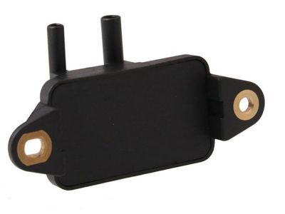
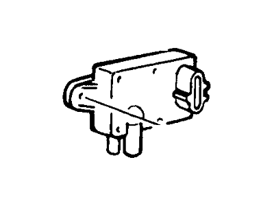
Make sure this part fits your vehicle

Mercury F4ZZ-9J460-B Sensor Assembly

1996-1999 Mercury F4ZZ9J460B

Ford F4ZZ-9J460-B Sensor Assembly
  • Part Description
    Sensor Assy
  • Replaced By
    F77Z-9J460-AB
  • Manufacturer
    Ford
Customer Questions & Answers
$70.51 MSRP: $116.55
You Save: $46.04 (40%)
1
ADD TO CART
Ships in 1 Business Day
  • Product Specifications

    BrandGenuine Mercury
    Manufacturer Part NumberF4ZZ-9J460-B, F4ZZ9J460B
    Part DescriptionSensor Assy
    Item Dimensions3.2 x 2.6 x 3.9 inches
    Item Weight0.40 Pounds
    ConditionNew
    Fitment TypeDirect Replacement
    ManufacturerFord
    SKUF4ZZ-9J460-B
    WarrantyThis genuine Ford part is guaranteed by Ford's factory warranty.
    Shipping & ReturnShipping Policy Return Policy
    Warning: California’s Proposition 65
  • Vehicle Fitment

    Year Make Model Engine Important vehicle option details
    1997-1998 Mercury Mountaineer8 Cyl 5.0L4AT 4R70W, 5AT 5R55E
    1996-1999 Mercury Mystique6 Cyl 2.5L4AT CD4E, 5MT

Customer Questions & Answers

Q:
Is the the correct part for the attached VIN? Posted by FordPartsGiant Specialist
A:
You can Select Your Vehicle to check if F4ZZ-9J460-B fits your vehicle.
Posted by FordPartsGiant Specialist
Q:
How to check Brake Light Switch,Coolant Temperature Sensor,EGR Valve Position Sensor,Intake Manifold Temperature Sensor,Knock Sensor,MAP Sensor,Mass Air Flow Sensor,Oxygen Sensors,Throttle Position Sensor on Ford Bronco? Posted by Customer
A:
When working with the PCM (also known as the EEC-V module) or associated harness, exercise caution to avoid direct contact with the electrical connector terminals, as static electricity can damage delicate electronic components inside the PCM. It is recommended to wear a static discharging wrist strap and avoid working on electronics when relative humidity is under 25 percent. General EEC-IV power relay and ground checks are essential to prevent confusion and inaccurate diagnosis. The EEC relay and associated circuits provide battery power (VPWR) to fuel injection and electric fuel pump-related components requiring 10.5 volts or greater. The PCM (EEC-IV) reduces the input voltage to four-to-six volts for output to sensors requiring a specific reference voltage (VREF). For fuel delivery component and circuit checks, verify proper electrical operation of the fuel pump relay, inertia switch, fuel pump(s), fuel injectors, and fuel tank selector switch on dual tank models. Information sensors and output actuators include the engine coolant temperature sensor, which is a thermistor varying its voltage output based on temperature changes. Resistance values change with temperature, and failure in the coolant sensor circuit may set a diagnostic code. To check the sensor, measure its resistance values when cold and at operating temperature, ensuring correct values. Verify the signal voltage to the sensor from the PCM, which should be approximately 5.0 volts. Before installing a new sensor, wrap the threads with Teflon sealing tape. The Manifold Absolute Pressure (MAP) sensor monitors intake manifold pressure changes and converts them into a voltage output. There are voltage-varying and frequency-varying types of MAP sensors. A failure in the MAP sensor circuit may set a diagnostic code. Check the reference voltage to the MAP sensor and back probe the harness to determine the sensor type. Test the sensor response with a tachometer and a handheld vacuum pump, ensuring a smooth transition between readings. Replace the MAP sensor if test results are incorrect. The heated oxygen sensor (HO2S) monitors the oxygen content of the exhaust gas stream, producing a voltage output that varies with the air-to-fuel ratio. Diagnostic codes indicate problems in the oxygen sensor system. Check the sensor's steady signal voltage between 0.35 and 0.55 volts at normal operating temperature. The sensor's proper operation depends on electrical connections, outside air supply, operating temperature, and the use of unleaded fuel. Take special care during sensor service to avoid damage. When replacing the oxygen sensor, use caution due to the sensor's location in the exhaust manifold or pipe. Start and run the engine briefly before removal to facilitate loosening. Disconnect the battery, raise the vehicle, disconnect the electrical connector, unscrew the sensor, apply anti-seize compound to the threads, install the new sensor, and reconnect the electrical connector. The Throttle Position Sensor (TPS) is located on the throttle body and monitors throttle valve angle, affecting fuel delivery. Problems in the TPS or circuit may set a diagnostic code. To check the TPS, measure the signal voltage at idle and full-open throttle positions. Verify the TPS reference voltage and resistance of the potentiometer within the TPS. Adjust the TPS if necessary. The Intake Manifold Temperature Sensor, also known as the Air Charge Temperature (ACT) sensor, is located in the intake manifold and acts as a resistor changing value with air temperature. Problems with the IAT sensor may set a diagnostic code. Check the reference voltage and measure resistance across the sensor terminals at different temperatures. Power steering pressure switch issues may cause timing to retard at idle or engine stalling under heavy power steering use. A pressure switch that fails to open or close may impact engine performance. Check for battery voltage to the power steering pressure switch and continuity to brake light bulbs. The Brake On/Off (BOO) switch indicates brake application to the PCM. Issues with the BOO switch or circuit may affect idle quality. Check for battery voltage to the BOO switch and continuity to brake light bulbs. The EGR Valve Position (EVP) sensor attached to the EGR valve produces a signal indicating the EGR valve's position. Check for reference voltage and resistance of the EVP sensor. Apply vacuum and check resistance change. Replace the EVP sensor if necessary. The Knock Sensor (KS) detects engine detonation, sending a voltage signal to the PCM to retard spark timing. Check for reference voltage to the knock sensor and simulate operating conditions to observe timing response. Replace the knock sensor if it does not respond. The Idle Air Control (IAC) or Bypass Air Idle Speed Control (BPA-ISC) solenoid controls idle speed by regulating air bypassing the throttle body. Check for the PCM signal voltage, inspect the pintle for carbon deposits, and check the resistance of the solenoid. Clean the IAC valve housing and install a new O-ring during replacement. The Mass Airflow (MAF) sensor measures air entering the engine using a hot wire sensing element. Check for power to the MAF sensor and voltage signals at idle and increased engine speed. Disconnect the MAF sensor and check for resistance. Replace the MAF sensor if necessary. The Manual Lever Position (MLP) sensor on the transmission indicates the gear position to the PCM. Check for power to each signal wire and adjust the switch if necessary. Further diagnostics require specialized equipment.
Posted by FordPartsGiant Specialist
Q:
How to remove and install Catalytic Converter, EGR Valve, EGR Valve Position Sensor and Vapor Canister on Ford Bronco? Posted by Customer
A:
To perform maintenance on the EGR system components, start by disconnecting the battery's negative terminal. For the EVP sensor, located on the EGR valve, unplug the electrical connector, remove the three mounting bolts, and detach the sensor, ensuring to use a new O-ring during installation. The EGR Control (EGRC) or EGR Vent (EGRV) Solenoid requires disconnecting the battery, locating the solenoid(s) on the firewall, unplugging the electrical connector, labeling and detaching vacuum hoses, and removing the solenoid(s) by unscrewing the bracket screws. The EGR Vacuum Regulator (EVR) solenoid, located on the engine-mounted solenoid bracket assembly, involves detaching the battery cable, unplugging the sensor harness electrical connector and vacuum hose, and removing the solenoid. The EGR valve, for vehicles with EEGR, necessitates unplugging the electrical connector from the EGR valve position sensor, unscrewing the threaded fitting for external exhaust supply tube (if present), removing the vacuum line and mounting bolts, detaching the valve, and replacing the gasket. If replacing the EGR valve without the position sensor, transfer the sensor to the new valve with a new O-ring. For Thermactor system components, such as the TAB/AIRB or TAD/AIRD solenoid, disconnect the battery, locate the solenoid(s) on the firewall, unplug the electrical connector, label and detach vacuum hoses, remove the solenoid/bracket screws, and detach the solenoid(s). Air pump and control valves on MTA systems involve labeling and disconnecting hoses, replacing the faulty component, and reattaching hoses. For the air supply pump on MTA systems, loosen drivebelts, remove the faulty pump, label hoses, install the new pump, and adjust drivebelts. Replacement of check valves requires using a back-up wrench if connected to a steel air tube. Charcoal canister replacement involves removing a single mounting bolt, lowering the canister, detaching the hose, and reinstalling in reverse. Other component replacements, such as those related to the air inlet control, deceleration throttle control, intake manifold heating, PCV system, and catalytic converter, follow straightforward procedures of disconnecting wires and hoses, removing faulty components, and installing new ones as needed.
Posted by FordPartsGiant Specialist
Q:
How to check Brake Light Switch,Coolant Temperature Sensor,EGR Valve Position Sensor,Intake Manifold Temperature Sensor,Knock Sensor,MAP Sensor,Mass Air Flow Sensor,Oxygen Sensors,Throttle Position Sensor on Ford F-250? Posted by Customer
A:
When working with the PCM (also known as the EEC-V module) or associated harness, exercise caution to avoid direct contact with the electrical connector terminals, as static electricity can damage delicate electronic components inside the PCM. It is recommended to wear a static discharging wrist strap and avoid working on electronics when relative humidity is under 25 percent. General EEC-IV power relay and ground checks are essential to prevent confusion and inaccurate diagnosis. The EEC relay and associated circuits provide battery power (VPWR) to fuel injection and electric fuel pump-related components requiring 10.5 volts or greater. The PCM (EEC-IV) reduces the input voltage to four-to-six volts for output to sensors requiring a specific reference voltage (VREF). For fuel delivery component and circuit checks, verify proper electrical operation of the fuel pump relay, inertia switch, fuel pump(s), fuel injectors, and fuel tank selector switch on dual tank models. Information sensors and output actuators include the engine coolant temperature sensor, which is a thermistor varying its voltage output based on temperature changes. Resistance values change with temperature, and failure in the coolant sensor circuit may set a diagnostic code. To check the sensor, measure its resistance values when cold and at operating temperature, ensuring correct values. Verify the signal voltage to the sensor from the PCM, which should be approximately 5.0 volts. Before installing a new sensor, wrap the threads with Teflon sealing tape. The Manifold Absolute Pressure (MAP) sensor monitors intake manifold pressure changes and converts them into a voltage output. There are voltage-varying and frequency-varying types of MAP sensors. A failure in the MAP sensor circuit may set a diagnostic code. Check the reference voltage to the MAP sensor and back probe the harness to determine the sensor type. Test the sensor response with a tachometer and a handheld vacuum pump, ensuring a smooth transition between readings. Replace the MAP sensor if test results are incorrect. The heated oxygen sensor (HO2S) monitors the oxygen content of the exhaust gas stream, producing a voltage output that varies with the air-to-fuel ratio. Diagnostic codes indicate problems in the oxygen sensor system. Check the sensor's steady signal voltage between 0.35 and 0.55 volts at normal operating temperature. The sensor's proper operation depends on electrical connections, outside air supply, operating temperature, and the use of unleaded fuel. Take special care during sensor service to avoid damage. When replacing the oxygen sensor, use caution due to the sensor's location in the exhaust manifold or pipe. Start and run the engine briefly before removal to facilitate loosening. Disconnect the battery, raise the vehicle, disconnect the electrical connector, unscrew the sensor, apply anti-seize compound to the threads, install the new sensor, and reconnect the electrical connector. The Throttle Position Sensor (TPS) is located on the throttle body and monitors throttle valve angle, affecting fuel delivery. Problems in the TPS or circuit may set a diagnostic code. To check the TPS, measure the signal voltage at idle and full-open throttle positions. Verify the TPS reference voltage and resistance of the potentiometer within the TPS. Adjust the TPS if necessary. The Intake Manifold Temperature Sensor, also known as the Air Charge Temperature (ACT) sensor, is located in the intake manifold and acts as a resistor changing value with air temperature. Problems with the IAT sensor may set a diagnostic code. Check the reference voltage and measure resistance across the sensor terminals at different temperatures. Power steering pressure switch issues may cause timing to retard at idle or engine stalling under heavy power steering use. A pressure switch that fails to open or close may impact engine performance. Check for battery voltage to the power steering pressure switch and continuity to brake light bulbs. The Brake On/Off (BOO) switch indicates brake application to the PCM. Issues with the BOO switch or circuit may affect idle quality. Check for battery voltage to the BOO switch and continuity to brake light bulbs. The EGR Valve Position (EVP) sensor attached to the EGR valve produces a signal indicating the EGR valve's position. Check for reference voltage and resistance of the EVP sensor. Apply vacuum and check resistance change. Replace the EVP sensor if necessary. The Knock Sensor (KS) detects engine detonation, sending a voltage signal to the PCM to retard spark timing. Check for reference voltage to the knock sensor and simulate operating conditions to observe timing response. Replace the knock sensor if it does not respond. The Idle Air Control (IAC) or Bypass Air Idle Speed Control (BPA-ISC) solenoid controls idle speed by regulating air bypassing the throttle body. Check for the PCM signal voltage, inspect the pintle for carbon deposits, and check the resistance of the solenoid. Clean the IAC valve housing and install a new O-ring during replacement. The Mass Airflow (MAF) sensor measures air entering the engine using a hot wire sensing element. Check for power to the MAF sensor and voltage signals at idle and increased engine speed. Disconnect the MAF sensor and check for resistance. Replace the MAF sensor if necessary. The Manual Lever Position (MLP) sensor on the transmission indicates the gear position to the PCM. Check for power to each signal wire and adjust the switch if necessary. Further diagnostics require specialized equipment.
Posted by FordPartsGiant Specialist
Q:
How to remove and install Catalytic Converter, EGR Valve, EGR Valve Position Sensor and Vapor Canister on Ford F-250? Posted by Customer
A:
To perform maintenance on the EGR system components, start by disconnecting the battery's negative terminal. For the EVP sensor, located on the EGR valve, unplug the electrical connector, remove the three mounting bolts, and detach the sensor, ensuring to use a new O-ring during installation. The EGR Control (EGRC) or EGR Vent (EGRV) Solenoid requires disconnecting the battery, locating the solenoid(s) on the firewall, unplugging the electrical connector, labeling and detaching vacuum hoses, and removing the solenoid(s) by unscrewing the bracket screws. The EGR Vacuum Regulator (EVR) solenoid, located on the engine-mounted solenoid bracket assembly, involves detaching the battery cable, unplugging the sensor harness electrical connector and vacuum hose, and removing the solenoid. The EGR valve, for vehicles with EEGR, necessitates unplugging the electrical connector from the EGR valve position sensor, unscrewing the threaded fitting for external exhaust supply tube (if present), removing the vacuum line and mounting bolts, detaching the valve, and replacing the gasket. If replacing the EGR valve without the position sensor, transfer the sensor to the new valve with a new O-ring. For Thermactor system components, such as the TAB/AIRB or TAD/AIRD solenoid, disconnect the battery, locate the solenoid(s) on the firewall, unplug the electrical connector, label and detach vacuum hoses, remove the solenoid/bracket screws, and detach the solenoid(s). Air pump and control valves on MTA systems involve labeling and disconnecting hoses, replacing the faulty component, and reattaching hoses. For the air supply pump on MTA systems, loosen drivebelts, remove the faulty pump, label hoses, install the new pump, and adjust drivebelts. Replacement of check valves requires using a back-up wrench if connected to a steel air tube. Charcoal canister replacement involves removing a single mounting bolt, lowering the canister, detaching the hose, and reinstalling in reverse. Other component replacements, such as those related to the air inlet control, deceleration throttle control, intake manifold heating, PCV system, and catalytic converter, follow straightforward procedures of disconnecting wires and hoses, removing faulty components, and installing new ones as needed.
Posted by FordPartsGiant Specialist
If you have any questions about this product, please don't hesitate to ask us. We will be happy to help you!

Genuine Ford Part F4ZZ-9J460-B, the Right Choice

Your vehicle deserves only genuine OEM Ford parts and accessories. To ensure reliability, purchase Ford part # F4ZZ-9J460-B Sensor Assembly. It is sometimes referred to as Mercury EGR Valve Position Sensor. Our Ford parts and accessories are expedited directly from authorized Ford dealers strategically located all across the U.S. and are backed by the manufacturer's 12 month, 12,000 mile warranty. OEM Ford parts are the best for restoring your vehicle to factory condition performance. This part fits specific Mercury Mountaineer, Mystique models.

Affordable, reliable and built to last, Ford part # F4ZZ9J460B Sensor Assembly stands out as the smart option. FordPartsGiant.com is your prime online source with the biggest and best selection of genuine Ford parts and accessories at giant discounted prices. We have the OEM Ford parts and accessories you need at the wholesale prices. FordPartsGiant.com has you covered no matter what type of Ford vehicle you drive. For detailed Mercury parts information, click here.

Why choose Ford Parts Giant

  • Dedicated Service

    Your complete satisfaction is our #1 goal

  • Lowest Prices

    Best deals on genuine OE parts from dealerships

  • Fast Delivery

    Orders are processed and delivered promptly