Make sure this part fits

Lincoln D9VZ-12A199-A Module Assembly - Ignition

1980-1984 Lincoln D9VZ12A199A

Customer Questions & Expert Answers (10)
D9VZ-12A199-A Ford Module Assembly - Ignition Product Photo 1 of 4
  • Part Description
    MODULE ASY - IGNITIO
  • Replaced By
    1U2Z-12A199-AA
  • Manufacturer
    Ford
Make sure this part fits
$62.83 MSRP: $93.64
You Save: $30.81 (33%)
1
ADD TO CART
  • Related Parts
  • Product Specifications
  • Vehicle Fitment
  • Customer Questions & Expert Answers
  • Product Specifications

    BrandGenuine Lincoln
    Manufacturer Part NumberD9VZ-12A199-A, D9VZ12A199A
    Part DescriptionMODULE ASY - IGNITIO
    Item Dimensions2.4 x 4.9 x 7.1 inches
    Item Weight0.80 Pounds
    ConditionNew
    Fitment TypeDirect Replacement
    ManufacturerFord
    SKUD9VZ-12A199-A
    WarrantyThis genuine Ford part is guaranteed by Ford's factory warranty.
    Shipping & ReturnShipping Policy Return Policy
    Warning: California's Proposition 65
  • Vehicle Fitment

    Year Make Model Engine Important vehicle option details
    1983-1984 Lincoln Continental8 Cyl 5.0L4AT AOD
    1982-1983, 1980 Lincoln Mark VI8 Cyl 5.0L, 8 Cyl 5.8L4AT AOD
    1982-1983 Lincoln Town Car8 Cyl 5.0L4AT AOD
    1980 Lincoln Versailles8 Cyl 5.0L3AT C4
  • Customer Questions & Expert Answers

    Q:
    I am wondering if this is the exact part that fits in Posted by FordPartsGiant Specialist
    A:
    You can Select Your Vehicle to check if D9VZ-12A199-A fits your vehicle.
    Posted by FordPartsGiant Specialist
    Q:
    How to remove and install the Ignition Control Module in a Ford Bronco II? Posted by Customer
    A:
    The negative battery cable must be disconnected. One has to detach the wiring harness connector(s) from the ICM. The ICM should be removed by taking out the mounting bolts. To reinstall, put the ICM into position and mount it using the bolts. Tighten the bolts to 22-31 inch lbs. Attach the wiring harness connector(s) to the ICM. Connect negative battery cable.
    Posted by FordPartsGiant Specialist
    Q:
    How to remove and install an ignition control module (ICM) or TFI ignition module on Ford Bronco II? Posted by Customer
    A:
    Disconnect the negative battery cable. Label and detach all wiring from the ICM. If the module is mounted to the inner fender, remove the ICM/heat sink-to-fender apron bolts, then remove the ICM/heat sink. If the module is mounted to the intake manifold, remove the ICM/heat sink-to-intake manifold bolts, then remove the ICM/heat sink. If necessary, at this time the ICM can be removed from the heat sink. Apply an approximately 1/32 in.(0.80mm) thick layer of silicone dielectric compound (D7AZ-19A331-A or equivalent) to the base plate of the ICM. Install the ICM onto the heat sink. Tighten the mounting bolts to 15-35 inch lbs. (1.7-4.0 Nm). Position the ICM onto the right-hand, front fender apron or intake manifold, then install and tighten the mounting bolts to 90-120 inch lbs. (10-14 Nm). Attach all wiring to the ICM, then connect the negative battery cable. Disconnect the negative battery cable. Remove the distributor assembly from the engine. Place the distributor on the workbench and remove the module retaining screws. Pull the right side of the module down the distributor mounting flange and back up to disengage the module terminal from the connector in the distributor base. The module may be pulled toward the flange and away from the distributor. Coat the base plate of the TFI ignition module uniformly with 1/32 inch of silicone dielectric compound WA-10 or equivalent. Position the module on the distributor base mounting flange. Carefully position the module toward the distributor bowl and engage the three connector pins securely. Install the retaining screws. Tighten to 15-35 inch lbs. (1.7-4.0 Nm), starting with the upper right screw. Install the distributor into the engine. Install the cap and wires. Reconnect the negative battery cable. Recheck the initial timing. Adjust if necessary.
    Posted by FordPartsGiant Specialist
    Q:
    How to replace Ignition Coil and Ignition Control Module on Ford F-250? Posted by Customer
    A:
    Before replacing ignition components, check for Federally mandated extended warranty eligibility. Be aware that disconnecting the battery may affect the Powertrain Control Module (PCM).To replace the Duraspark ignition coil, disconnect the negative battery cable, mark coil wires, remove high-tension lead and coil connections, and remove coil bracket bolts. Install a new coil with silicone grease inside the high-tension lead boot.To replace the Duraspark ignition module, disconnect the negative battery cable, unplug module connectors, remove mounting screws, and install the new module.For the Duraspark stator assembly, remove negative battery cable, distributor components, armature, E-clip, ground strap screw, wire retaining clip, and stator assembly. Clean and reinstall the lower plate assembly, stator assembly, armature, and other components.For V6 engines, similar steps apply, but include additional steps to remove the lower plate assembly and stator assembly.For the TFI-IV ignition coil, locate coil assembly, unplug the connector and wire, remove screws, detach coil, and install new coil with silicone dielectric grease in the coil-to-distributor lead boot.To replace the TFI-IV ignition control module, follow the specified steps for removal and installation. Apply silicone dielectric grease to the module's back.For TFI-IV or DI distributor stator replacement, remove distributor cap and wires, follow steps for stator assembly removal and installation. Check for wear and replace faulty parts.
    Posted by FordPartsGiant Specialist
    Q:
    How to diagnose and replace the ignition control module on the Lincoln Continental? Posted by Customer
    A:
    The ignition control module is a delicate and relatively expensive electronic component, and improper procedures could lead to damage to the module or other electronic devices, including the EEC-IV microprocessor. Check with your dealer about the Federally mandated extended warranty on devices under computer control before attempting to diagnose and replace the module yourself. Note that certain models use a special DuraSpark II ignition control module with altitude compensation features for spark timing and engine performance at high altitudes. An intermittent no-start condition may occur in some years and models of SSI and DuraSpark ignition systems, where the engine starts momentarily and shuts down instantly or runs the duration of a trip but won't restart afterward. Striking the module or applying heat won't fix it, confirming the ignition control module as defective. To check the ignition control module on DuraSpark systems, examine power to the module, resistance of the distributor stator, and ground circuit continuity. For TFI-IV ignition control modules, inspect power, resistance between terminals, and the PIP to SPOUT circuit. Always ensure safety measures when working with the ignition system. For ignition control module replacement, detach the negative battery cable, unplug electrical connectors, remove mounting screws, and replace the module or stator. Reassemble components following the reverse order of removal and use appropriate lubrication or dielectric grease when specified.
    Posted by FordPartsGiant Specialist
    Q:
    How to test and replace the Ignition Control Module on the Mercury Lynx? Posted by Customer
    A:
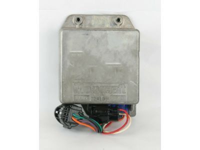
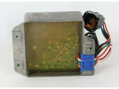
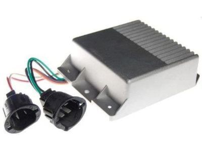
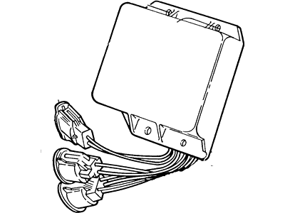
    Caution is advised as the ignition control module is a delicate and relatively expensive electronic component, requiring tests to be performed with the appropriate equipment by knowledgeable individuals. Failure to adhere to the outlined procedures may lead to damage to the module or other electronic devices, including the EEC-IV microprocessor in TFI vehicles. All devices under computer control are protected by a Federally mandated extended warranty, so consulting a dealer before attempting self-diagnosis is recommended. To check the Duraspark II system ignition control module voltage, turn off the ignition switch, insert a small straight pin into the red module wire without grounding it, attach the negative lead of a voltmeter to the distributor base, measure battery voltage, and then attach the positive lead to the pin in the red module wire with the ignition switch in the Run position. If the measured voltage is less than 90 percent of the battery voltage, inspect the wiring harness and ignition switch for wear and damage. For the ignition control module wiring harness, attach one lead of an ohmmeter to the distributor base and check the resistance between the wiring harness terminals mating with the black and purple module wires. If the resistance is greater than the specified value, the ignition control module-to-distributor stator wiring harness resistance is normal; otherwise, inspect the wiring harness. Unplug and inspect the four-wire ignition control module electrical connector and the ignition coil connector, then measure the resistance between the TACH terminal of the ignition coil connector and ground. If the resistance is greater than one ohm, replace the ignition control module; if less, inspect the wiring harness. For the ground circuit, insert a small straight pin into the black module wire, attach the negative lead of a voltmeter to the distributor base, and measure the voltage at the black wire. If the voltage is greater than 0.5 volt, check the distributor ground circuit; if less, replace the ignition control module. Unplug the electrical connector from the distributor and inspect it, then measure the resistance in the distributor ground circuit. If the resistance is less than one ohm, the circuit is okay; if greater, check the ground screw in the distributor. For the TFI-I system, remove the distributor and ignition control module, check the condition of the distributor ground screw, stator wires, and connector terminals, and connect an ohmmeter between the stator terminals. For the TFI-IV system, unplug the wiring harness connector from the ignition control module, inspect it, and check for spark using a calibrated spark tester. If there is no spark, proceed to the distributor/TFI-IV module check. If spark is present, the issue may lie with the inferred mileage sensor or the EEC-IV electronic control module, which requires professional diagnosis. For models from 1984 to 1987, purchase a new ignition control module before performing checks, as the process may necessitate a new module. For models from 1987 to 1990, measure resistance between the ignition control module terminals in various ignition switch positions; if resistance is as listed, the module is good, and the stator is defective. For module replacement in the Duraspark II system, detach the cable from the negative terminal of the battery, unplug the appropriate connectors, remove the mounting screws, and detach the module, ensuring installation is the reverse of removal. For TFI and TFI-IV systems, remove the distributor, unscrew the module mounting screws, and disconnect the spade connectors from the stator connector, applying silicone dielectric grease to the back side of the module before installation.
    Posted by FordPartsGiant Specialist
    Q:
    How to diagnose and replace the Ignition Control Module on the Lincoln Town Car? Posted by Customer
    A:
    The ignition control module is a delicate and relatively expensive electronic component, and improper procedures could lead to damage to the module or other electronic devices, including the EEC-IV microprocessor. Check with your dealer about the Federally mandated extended warranty on devices under computer control before attempting to diagnose and replace the module yourself. Note that certain models use a special DuraSpark II ignition control module with altitude compensation features for spark timing and engine performance at high altitudes. An intermittent no-start condition may occur in some years and models of SSI and DuraSpark ignition systems, where the engine starts momentarily and shuts down instantly or runs the duration of a trip but won't restart afterward. Striking the module or applying heat won't fix it, confirming the ignition control module as defective. To check the ignition control module on DuraSpark systems, examine power to the module, resistance of the distributor stator, and ground circuit continuity. For TFI-IV ignition control modules, inspect power, resistance between terminals, and the PIP to SPOUT circuit. Always ensure safety measures when working with the ignition system. For ignition control module replacement, detach the negative battery cable, unplug electrical connectors, remove mounting screws, and replace the module or stator. Reassemble components following the reverse order of removal and use appropriate lubrication or dielectric grease when specified.
    Posted by FordPartsGiant Specialist
    Q:
    How to replace the Ignition Control Module on the Mercury Capri? Posted by Customer
    A:
    The ignition control module is a delicate and relatively expensive electronic component. Failure to follow the procedures could result in damage to the module or other electronic devices, including the EEC-IV microprocessor itself. Additionally, all devices under computer control are protected by a Federally mandated extended warranty. Check with your dealer before attempting to replace them yourself. Duraspark I and II ignition control module: Detach the cable from the negative terminal of the battery. Vehicles equipped with a Duraspark I or II system may have either the standard Duraspark I or II module or the universal ignition control module. If your vehicle is equipped with the standard module, unplug both connectors; if your vehicle is equipped with the UIM module, unplug all three connectors. Remove the mounting screws and detach the module. Installation is the reverse of removal. TFI-IV ignition control module: Remove the distributor from the engine if access to the module is blocked. Remove the two module mounting screws with a 1/4-inch drive 7/32-inch deep socket. Pull straight down on the module to disconnect the spade connectors from the stator connector. Whether you are installing the old module or a new one, wipe the back side of the module clean with a soft, clean rag and apply a film of silicone dielectric grease to the backside of the module. Installation is the reverse of removal. When plugging in the module, make sure that the three terminals are inserted all the way into the stator connector. Disconnect the negative cable from the battery. Disconnect the electrical connector from the EDIS ignition control module. Remove the screws securing the EDIS module to the lower intake manifold. Installation is the reverse of the removal procedure. Prior to installing the EDIS module onto the manifold, apply about a 1/32-inch of silicone dielectric compound to the mounting surface of the module.
    Posted by FordPartsGiant Specialist
    Q:
    How to remove the Ignition Control Module on Ford Thunderbird? Posted by Customer
    A:
    To remove the heatsink assembly, unscrew or unbolt it from the radiator support bracket on non-supercharged models or the belt pulley bracket on supercharged models. On non-supercharged models, remove the two screws holding the ignition control module to the heatsink. Disconnect the electrical connector from the ignition control module. Before installation, coat the metal baseplate of the ignition control module with silicone dielectric compound WA-10, D7AZ-19A331-A or equivalent. To reinstall, follow the reverse of the removal procedure.
    Posted by FordPartsGiant Specialist
    Q:
    How do you replace the TFI-IV ignition control module for the 1986 Ford Bronco? Posted by Customer
    A:
    For the TFI-IV ignition control module (distributor-mounted or remote-mounted), follow the specified steps for removal and installation. Apply silicone dielectric grease to the back of the module before installing it.
    Posted by FordPartsGiant Specialist
    See expert answers on similar Ignition Control Module
    If you have any questions about this product, please don't hesitate to ask us. We will be happy to help you!

Genuine Ford Part D9VZ-12A199-A, the Right Choice

To ensure reliability, purchase part # D9VZ-12A199-A Module Assembly - Ignition. It is also called Ignition Control Module. OEM parts are of high quality and known for their longevity. This is because they are built to the Ford standards which are relatively high and undergo rigorous quality control testing. This part fits specific Lincoln Continental, Mark VI, Versailles models.

FordPartsGiant.com is a leading supplier of genuine components and accessories such as D9VZ12A199A Module Assembly - Ignition. Looking to purchase quality low-cost OEM Ford parts? You have just found the right place. For detailed Lincoln parts information, click here.

Why choose Ford Parts Giant

  • Dedicated Service

    Your complete satisfaction is our #1 goal

  • Lowest Prices

    Best deals on genuine OE parts from dealerships

  • Fast Delivery

    Orders are processed and delivered promptly