My Garage
My Account
Cart
This part fits
2010 Ford Fusion
Check another vehicle- Fit Note: Ford Division Derivative, Lincoln Division Derivative, Mercury Division Derivative
- Production Date: 08/2009-07/2012
Ford 9E5Z-15604-F Door Lock And Alarm Module
2010-2012 Ford 9E5Z15604F
Customer Questions & Expert Answers (2)
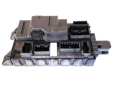
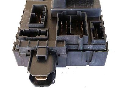
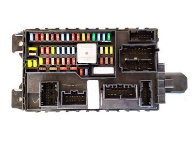
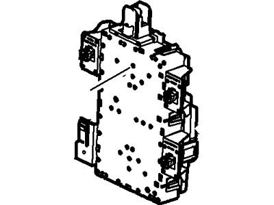
- Part DescriptionModule - Door Lock And Alarm
- Smart Junction Box
- Replaces
- ManufacturerFord
- Manufacturer's NotesThis part is discontinued.
This part fits
2010 Ford Fusion
Check another vehicle- Fit Note: Ford Division Derivative, Lincoln Division Derivative, Mercury Division Derivative
- Production Date: 08/2009-07/2012
- Related Parts
- Specifications
- Q&A
Product Specifications
Brand Genuine Ford Manufacturer Part Number 9E5Z-15604-F, 9E5Z15604F Part Description Module - Door Lock And Alarm Other Names Control Module, Receiver Manufacturer Note Smart Junction Box Item Dimensions 9.0 x 4.5 x 14.8 inches Item Weight 2.40 Pounds Condition New Fitment Type Direct Replacement Replaces 9E5Z-15604-C, 9E5Z-15604-A, 9E5Z-15604-E, 9E5Z-15604-D Manufacturer Ford SKU 9E5Z-15604-F Warranty This genuine Ford part is guaranteed by Ford's factory warranty. Shipping & Return Shipping Policy Return Policy Warning: California's Proposition 65Customer Questions & Expert Answers
- Q:I would like to know is this part gonna fit with my car Posted by FordPartsGiant Specialist
- A:You can Select Your Vehicle to check if 9E5Z-15604-F fits your vehicle.Posted by FordPartsGiant Specialist
- Installation and Repair Tips by AI Expert
- Removal steps 1. Park on a level surface, set the parking brake, remove the key, and block the wheels. 2. Disconnect the negative battery cable and move it clear of the terminal; if the vehicle interfaces with SRS or high-voltage systems, follow manufacturer safety procedures and allow the vehicle electronics to power down fully. 3. Remove any trim or access panels needed to reach the module using appropriate trim tools; panel locations and fasteners vary by design. 4. Photograph and label each wiring connector and harness orientation before you touch them. 5. Release connector locking tabs and disconnect harnesses carefully, pulling on the connector body only and avoiding wire damage. 6. Remove the fasteners securing the module (fastener type and location vary) while supporting the module so it cannot fall. 7. Withdraw the module and place it on a static-safe, nonconductive surface; keep mounting hardware and clips together. Installation steps 1. Inspect the replacement module and mating connectors for damage, dirt, or corrosion; clean connectors if needed. 2. Position the module into its mounting location and start the fasteners by hand to avoid cross-threading. 3. Secure the fasteners snugly - do not guess torque values; tighten to factory specifications when available. 4. Reconnect the wiring harnesses, ensuring each connector is fully seated and the locking tabs engage. 5. Reinstall any trim or access panels removed earlier, retaining clips and screws. 6. Reconnect the negative battery cable last and ensure the battery is secure. 7. Power up the vehicle, allow modules to wake, and use a diagnostic scanner to confirm BCM communication, clear fault codes, and check affected functions (lighting, locks, windows, SRS, etc.). 8. Perform a functional check and short road test of related systems to verify normal operation. 9. Repair tip: protect against static discharge when handling the module, keep connectors clean, and consider dielectric grease on terminals if recommended for the vehicle.
- Q:
Why choose Ford Parts Giant
- Dedicated Service
Your complete satisfaction is our #1 goal
- Lowest Prices
Best deals on genuine OE parts from dealerships
- Fast Delivery
Orders are processed and delivered promptly