

My Garage
My Account
Cart
Additional information needed to check if this part fits
2010 Ford Taurus
Check another vehicle- Fitting Vehicle Options: 6 Cyl 3.5L DOHC T/C
- Production Date: 06/2009-07/2010
Ford AA5Z-9F593-C Injector Assembly
2010-2011 Ford AA5Z9F593C
Customer Questions & Expert Answers (3)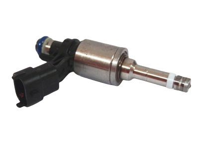
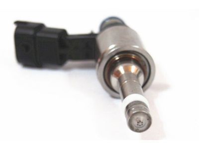
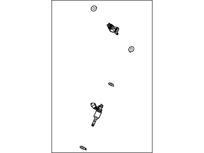
- Part DescriptionInjector Assy
- Replaced By
- ManufacturerFord
- Require Quantity6
- Package Quantity1
Additional information needed to check if this part fits
2010 Ford Taurus
Check another vehicle- Fitting Vehicle Options: 6 Cyl 3.5L DOHC T/C
- Production Date: 06/2009-07/2010
$179.58 MSRP: $290.91
You Save: $111.33 (39%)
Ships in 1-2 Business Days
1
- Related Parts
- Specifications
- Q&A
Product Specifications
Brand Genuine Ford Manufacturer Part Number AA5Z-9F593-C, AA5Z9F593C Part Description Injector Assy Item Dimensions 3.8 x 2.4 x 2.4 inches Item Weight 0.50 Pounds Condition New Fitment Type Direct Replacement Require Quantity 6 Manufacturer Ford SKU AA5Z-9F593-C Warranty This genuine Ford part is guaranteed by Ford's factory warranty. Shipping & Return Shipping Policy Return Policy Warning: California's Proposition 65Customer Questions & Expert Answers
- Q:Will these fit my car and if not which part will? Thank you. Posted by FordPartsGiant Specialist
- A:You can Select Your Vehicle to check if AA5Z-9F593-C fits your vehicle.Posted by FordPartsGiant Specialist
Installation and Repair Tips- Q:How to remove and install fuel injectors and the fuel rail on Ford Taurus? Posted by Customer
- A:To begin, relieve the fuel system pressure and disconnect the cable from the negative battery terminal. For four-cylinder models, remove the intake manifold, disconnect the high-pressure fuel line from the fuel pump and fuel rail, and disconnect the electrical connectors for all wiring associated with the fuel injectors, followed by the four fuel injector electrical connectors. Use a trim removal tool to disengage the retainers securing the wiring harness to the fuel rail, then clean the area around each injector with compressed air. Remove and discard the fuel rail mounting fasteners, then take out the fuel rail and injectors, using new bolts for installation. If the fuel injectors remain in the cylinder heads, use a removal tool to extract them. Remove the old combustion chamber Teflon sealing ring, upper O-ring, and support ring from each injector, taking care not to damage the groove for the seal. Clean the groove and injector shaft thoroughly before installing the new Teflon seal using the recommended special tools or an alternative method with a socket. After installing the new seals, lubricate the new upper O-ring with clean engine oil and install it on the injector, ensuring the O-ring is above the support ring. Clean the injector bores, insert each injector into its bore in the fuel rail, and secure them with retaining clips. Install the injectors and fuel rail assembly on the cylinder head, tightening the mounting fasteners in the correct sequence. For V6 models, remove the appropriate intake manifold, disconnect the fuel supply line and electrical connectors, detach the retainers, and remove the fuel rail and injectors as a single assembly. Release the injector retaining clips and remove each injector, discarding the old O-rings. Coat the new O-rings with clean engine oil and install them on the injectors, then secure the injectors to the fuel rail. Install the intake manifold gaskets if necessary, attach the fuel rail assembly, and tighten the bolts. Finally, reconnect the cable to the negative battery terminal, turn the ignition switch to ON to activate the fuel pump, and check for fuel leaks.Posted by FordPartsGiant Specialist
- Additional Installation and Repair Tips by AI Expert
- Removal steps 1. Park on a level surface, set the parking brake, wear safety glasses and gloves, and work in a well-ventilated area away from open flames. 2. Allow the engine to cool and relieve fuel system pressure using an approved method (this commonly involves disabling the fuel pump and cycling the ignition or using a fuel pressure gauge). 3. Disconnect the negative battery cable and isolate the battery before touching electrical connectors. 4. Remove or move any engine covers, intake components, or brackets that restrict access to the fuel rail/injectors; the exact items will vary by design. 5. Label and disconnect electrical connectors and any vacuum or sensor lines attached to the fuel rail or injectors to avoid mix-ups. 6. Place shop rags or a drip tray under the work area and be prepared to catch residual fuel when lines are opened. 7. Carefully loosen and remove fuel rail mounting fasteners and any fuel line fittings as required; support the rail so it does not bend or drop. 8. Remove retaining clips (if present) and pull each injector straight out of the rail and intake/tube assembly, keeping orientation consistent; handle injectors by the plastic body, not the pintle. 9. Remove and discard old O-rings and seals and inspect injectors and mounting bores for damage or heavy deposits. Installation steps 1. Verify replacement injectors match the originals visually and that new O-rings/seals are included. 2. Clean mounting bores with lint-free rags and compressed air, keeping debris out of the intake or fuel passages. 3. Lightly lubricate new O-rings with a small amount of clean engine oil or manufacturer-approved lubricant to prevent tearing during installation. 4. Install new O-rings/seals onto each injector and seat them properly without twisting. 5. Position injectors into the fuel rail/manifold straight and press them in until seated; reinstall retaining clips if used. 6. Reinstall the fuel rail, align parts, and snug fasteners evenly; do not force components-tighten to manufacturer guidance (do not guess torque values). 7. Reconnect fuel lines, vacuum lines, sensors, and electrical connectors, ensuring secure engagement and correct routing. 8. Reconnect the negative battery cable. 9. Prime the fuel system (commonly by switching the ignition to ON several times without starting) and inspect all connections for leaks while the system is pressurized. 10. Start the engine, check for fuel leaks, verify smooth idle and drivability, and scan for diagnostic trouble codes; address any leaks or codes before road testing. Repair tip: Replace injector O-rings and retaining hardware whenever injectors are serviced, keep dirt away from injector tips, and dispose of fuel-soaked rags safely.
- Q:
Why choose Ford Parts Giant
- Dedicated Service
Your complete satisfaction is our #1 goal
- Lowest Prices
Best deals on genuine OE parts from dealerships
- Fast Delivery
Orders are processed and delivered promptly