This part fits the vehicle you selected:
My Vehicle: 2006 Ford Mustang
Change VehicleThe vehicle options this part fits:
- Production Date: 09/2004-06/2014
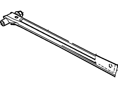
Ford 4R3Z-4264-AA Bar - Rear Stabilizer
2005-2014 Ford Mustang 4R3Z4264AA

- Part DescriptionBar - Rear Stabilizer
- Lateral Stiffener Bar
- Base No.4264B
- PositionRear
- ManufacturerFord
This part fits the vehicle you selected:
2006 Ford Mustang
The vehicle options this part fits:
- Production Date: 09/2004-06/2014
$31.24 MSRP: $44.50 1
You Save: $13.26 (30%)
Ships in 1-3 Business Days
Product Specifications
| Brand | Genuine Ford |
| Base No. | 4264B |
| Manufacturer Part Number | 4R3Z-4264-AA, 4R3Z4264AA |
| Part Description | Bar - Rear Stabilizer |
| Other Names | Track Bar |
| Item Weight | 2.90 Pounds |
| Position | Rear |
| Condition | New |
| Fitment Type | Direct Replacement |
| Manufacturer | Ford |
| SKU | 4R3Z-4264-AA |
| Warranty | This genuine Ford part is guaranteed by Ford's factory warranty. |
| Shipping & Return | Shipping Policy Return Policy |
Warning: California’s Proposition 65
Customer Questions & Answers
- Q:Is the the correct part for the attached VIN? Posted by FordPartsGiant Specialist
- A:You can Select Your Vehicle to check if 4R3Z-4264-AA fits your vehicle.Posted by FordPartsGiant Specialist
- Q:How to replace the control arms, lateral stiffener,Trailing Arm and Panhard rod on a Ford Mustang? Posted by Customer
- A:With the vehicle on the ground and at normal ride height, mark the shock absorbers in relation to the dust sleeve. Loosen the wheel lug nuts, raise the rear of the vehicle and support it securely on jackstands placed under the frame. Remove the wheels. On convertible models, remove the rear support braces. For the upper control arm, remove the rear seat and then remove the upper control arm front bolt. Discard the bolt. Support the fuel tank and remove the two rear fuel tank strap fasteners. Lower the fuel tank enough for access to the upper control arm mounting fasteners. Remove the upper control arm-to-rear axle pivot bolt and nut. Do not remove the other pivot bolt that attaches the control arm to the mount through the arm bushing. The angle of the arm and mount are set during production and affect the ride height of the vehicle. If the bushing between the control arm and mount is damaged, replace the bushing, arm and mount as a single unit. Unscrew the fasteners for the control arm assembly and remove the arm. Inspect the bushings in the control arm assembly and at the differential housing. If either bushing is damaged or worn, the control arm assembly or the bushing at the differential housing will have to be replaced. Position the control arm assembly and install new mounting fasteners to the chassis. Tighten the fasteners to the torque. Carefully raise the axle so that the marks on the shock absorbers line up with the dust sleeves, then install the control arm-to-rear axle pivot bolt. Tighten the fasteners to the torque. For the lower control arm, detach the parking brake cable from the caliper. Remove the parking brake cable bracket fastener and remove the bracket located in front of where the lower control arm attaches to the chassis. Place two floor jacks under the axle tubes to support it. Remove the lower control arm mounting fasteners, then remove the lower arm. Discard the fasteners. Inspect the bushings at both ends of the arm. If either bushing is damaged or worn, the trailing arm will require replacement. To install the arm, position it in the frame and axle mounting brackets and install new fasteners. Do not tighten the fasteners at this time. Carefully raise the axle so that the marks on the shock absorbers line up with the dust sleeves, then tighten the lower control arm mounting fasteners to the torque. For the lateral stiffener, place two floor jacks under the axle tubes to support it. Remove the Panhard rod-to-body mounting fasteners, then remove the lateral stiffener mounting fasteners. Discard the fasteners. Remove the lateral stiffener. To install the stiffener, position it to the frame and install new fasteners. Tighten the fasteners to the torque. Install new Panhard rod-to-body fasteners but do not tighten them yet. Carefully raise the axle so that the marks on the shock absorbers line up with the dust sleeves and then tighten the Panhard rod-to-body mounting fasteners to the torque. For the Panhard rod, place two floor jacks under the axle tubes to support it. Remove the Panhard rod-to-axle and Panhard rod-to-body mounting fasteners and then remove the rod. Discard the fasteners. Remove the plastic cover over the Panhard rod-to-axle mounting fasteners by inserting screwdrivers into the access slots to release the retaining clips, if equipped. To install the Panhard rod, position it to the frame and axle and install new mounting fasteners but do not tighten them yet. Carefully raise the axle so that the marks on the shock absorbers line up with the dust sleeves, then tighten the Panhard rod-to-axle and Panhard rod-to-body mounting fasteners to the torque. Replace the plastic cover over the Panhard rod-to-axle mounting fasteners, if equipped.For all components, on convertible models, reinstall the rear support braces. Install the wheel and lug nuts. Remove the jackstands and floor jacks, lower the vehicle and tighten the lug nuts to the torque.Posted by FordPartsGiant Specialist
If you have any questions about this product, please don't hesitate to ask us. We will be happy to help you!
Why choose Ford Parts Giant
- Dedicated Service
Your complete satisfaction is our #1 goal
- Lowest Prices
Best deals on genuine OE parts from dealerships
- Fast Delivery
Orders are processed and delivered promptly

