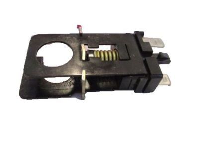
Genuine Ford F-250 Brake Light Switch
Brake Lamp SwitchEnter your vehicle info to find more parts and verify fitment
- Select Vehicle by VIN
- Select Vehicle by Model
Select by VIN
orEnter your VIN for the most accurate results.Enter your VIN for the most accurate results.
Select by Model
-- Select Make --
-- Select Model --
-- Select Year --
2 Brake Light Switches found
Ford F-250 Switch Assembly - Stop Light
Part Number: E9AZ-13480-A- Other Name: Switch Assy - Stop Light; Stoplamp Switch
$15.96 MSRP: $25.45You Save: $9.49 (38%)
Ford F-250 Switch Assembly - Stop Light
Part Number: E9LY-13480-A- Other Name: Switch Assy - Stop Light; Stoplamp Switch
Ford F-250 Brake Light Switch Parts Questions & Answers
- Q: What is the location and function of the brake light switch on Ford F-250?A: The brake light switch is located under the dashboard above the Brake Pedal. It is activated when the pedal moves away from its bottomed position, closing an electrical circuit. The switch is mounted in a metal bracket that can be adjusted by bending it. Ensure the switch is fully seated in the bracket and use an assistant, mirror, or test light to determine when the brake light circuit is activated. The switch should activate within the first 1/4-inch of pedal travel. If not, bend the bracket up or down to achieve the desired results, but avoid preventing the pedal from fully returning. The factory recommends a 25-pound or less pull up on the pedal to adjust the switch. Always ensure the brake lights are off when the pedal is at rest.
- Q: How to check Brake Light Switch,Coolant Temperature Sensor,EGR Valve Position Sensor,Intake Manifold Temperature Sensor,Knock Sensor,MAP Sensor,Mass Air Flow Sensor,Oxygen Sensors,Throttle Position Sensor on Ford F-250?A: When working with the PCM (some call it the EEC-V module) or its related harness, be careful not to touch directly any terminal on the electrical connector as static electricity could damage the PCM's delicate electronic components. It is recommended that you wear a static discharging wrist strap and do not work on electronics when relative humidity of less than 25% is experienced. There must be checks for general EEC-IV power relay and ground to avoid confusion or misdiagnosis. Battery powered fuel injection and electric Fuel Pump related components requiring 10.5 volts or above are provided by EEC relay and associated circuits. The PCM (EEC-IV) reduces input voltage to four-to-six volts for output to sensors requiring specific reference voltage (VREF). For checking fuel delivery component(s), verify proper electrical operation of the following: Dual tank models should have their fuel pumps relays, inertia switches, fuel pump(s), Fuel Injectors, and fuel tanks selector switch checked correctly during circuit checks for these components. Information sensors and output actuators include engine coolant temperature sensor which varies its voltage output based on temperature changes like a thermistor does. Resistances change with temperatures; coolant sensor circuit failures may set diagnostic code. For cold-started measurements of resistance values in order to establish if it is within correct ranges at operating temperature provide suitable data against which one can test the sensor's performance before confirming its current status too. Verify about 5 volts signal voltage from PCM to sensor. Always wrap new sensors' threads with Teflon sealing tape when installing them into exhaust manifolds .The Manifold Absolute Pressure (MAP) sensor senses intake manifold pressure variation then converts them into voltage output signals .Voltage varying type MAP sensors are also available as well as frequency varying types too. A failure in MAP sensor circuitry however might lead to diagnostic trouble code creation .Check reference voltage to MAP sensor after back probing wiring harness for determining type of sensor. Use a tachometer and a hand held vacuum pump to test the response of this device, verifying that it changes smoothly from one reading into another. Replace the MAP sensor if necessary results show malfunctioning. The heated oxygen sensor (HO2S) monitors the oxygen content of the exhaust gas stream, producing a voltage output that varies with air fuel ratio .Diagnostic codes indicate problems in the oxygen sensor system. Check their signal voltage stability between 0.35 and 0.55 volts at normal operating temperature. Sensor operation depends on electrical connections, outside air supply, operating temperature, and unleaded fuel use .Take special care during servicing sensors so as not to damage them. Prior replacing O2 sensors caution should be taken because they are located in exhaust manifold or pipe itself .Start and run engine briefly before removal to facilitate loosening. Make sure to disconnect battery, lift vehicle off ground , disconnect electrical connector, unscrew sensor from its position , apply anti-seize compound on threads of new sensor then install it , reconnect electrical connector.The Throttle Position Sensor (TPS) located on throttle body measures angle of throttle valve which affect how much fuel is delivered.Problems in TPS or circuitry may result in diagnostic trouble code being set To check the TPS measure signal voltage at idle and full-open throttle positions Verify reference voltage for TPS and resistance across potentiometer within it Adjust TPS when required.The Intake Manifold Temperature Sensor also known as Air Charge Temperature (ACT) sensor is a resistor changing value with air temperature placed inside intake manifold .Intake Manifold Temperature Sensor malfunction may produce diagnostic trouble code.Check reference voltage and measure resistance across terminals at different temperatures.Power steering pressure switch issues may cause timing to retard at idle or engine stalling under heavy power steering use A pressure switch that fails to open or close may impact engine performance.Verify battery voltage for power steering pressure switch along with continuity to brake light bulbs. The Brake Light Switch indicates brake application to the PCM. Issues with the Brake Light Switch or circuit may affect idle quality. Check battery voltage for Brake Light Switch and continuity to brake light bulbs.The EGR Valve Position (EVP) sensor attached to the EGR valve produces a signal indicating the EGR valve's position. Check reference voltage and resistance of EVP sensor Apply vacuum and check resistance change Replace EVP sensor if necessary .The Knock Sensor (KS) detects engine detonation, sending a voltage signal to the PCM to retard spark timing.Check reference voltage for knock sensor and simulate operating conditions for timing response Replace KS if it does not respond.Idle Air Control (IAC) or Bypass Air Idle Speed Control (BPA-ISC) solenoid controls idle speed by regulating air bypassing throttle body.Check PCM signal voltage, inspect pintle for carbon deposits, measure solenoid resistance Clean IAC valve housing during installation and install new O-ring.Mass Airflow (MAF) sensor measures air entering the engine using a hot wire sensing element .Check power supply to MAF sensor and voltage signals at idle as well as increased engine speed.Disconnect MAF sensor then test its resistance.Replace MAF sensor where necessary.The Manual Lever Position (MLP) sensor on transmission indicates gear position being sent out through PCM Let each signal wire get power before having switch adjusted Further diagnostics require specialized equipment.

Related Ford F-250 Parts
 Ford F-250 Neutral Safety Switch
 Ford F-250 Mirror Switch
 Ford F-250 Seat Switch
 Ford F-250 Door Jamb Switch
 Ford F-250 Oil Pressure Switch
 Ford F-250 Turn Signal Switch
 Ford F-250 Headlight Switch
 Ford F-250 Back Up Light Switch
 Ford F-250 Wiper Switch
Browse by Year
1999 Brake Light Switch 1998 Brake Light Switch 1997 Brake Light Switch 1996 Brake Light Switch 1995 Brake Light Switch 1994 Brake Light Switch 1993 Brake Light Switch 1992 Brake Light Switch 1991 Brake Light Switch 1990 Brake Light Switch 1989 Brake Light Switch 1988 Brake Light Switch 1987 Brake Light Switch 1986 Brake Light Switch